
|
|
Forum Index : Microcontroller and PC projects : Pineapple Controller 1
| Page 1 of 2 |
|||||
| Author | Message | ||||
| Mixtel90 Guru Joined: 05/10/2019 Location: United KingdomPosts: 8911 |
This is intended to be the replacement for the aquarium controller that I built some time ago. That had a few failings when I finally got round to using it, not least the reliability of WiFi on it. I decided that a simple display together with the ability to set the time without connecting it to a PC would probably be enough. Then I started thinking about changing the lighting. Originally the tank had just a white top light, which was insufficient for growing plants, especially as the back of the tank was in shadow from a rather nice filter system that runs the length of the tank just above the surface of the water. This is a 5V fitting. I added a commercial RGB fitting closer to the front of the tank and lower, to both boost the light level and shine some of it back into the tank. That is 12V. The aquarium controller had too much volt drop for the white fitting and I eventually had to disconnect the ULN chip and lace a mosfet up underneath the board. The latest idea is to have both a white 12V strip and a WS2812B strip in the same tube, slightly bigger than the original white light and mounted a bit lower. A second strip of WS2812B fires upwards along the back onto a light grey card, giving a programmable backlight. I experimented with this and it looks good. It doesn't need much brightness so there isn't a lot of load on the 5V rail. 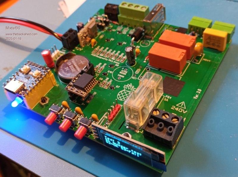 The prototype version is runnable, but I've made several enhancements to it since. I've made it more general purpose, hence giving this board its own thread. I've also created a test program so if you build one you can check that it works before using it in a project. It's handy to have in a flash slot as you can toggle the outputs. I did this to close the relays when insulation testing the mains side. Have a construction pack. :) pineaple 1 controller construction pack.zip Mick Zilog Inside! nascom.info for Nascom & Gemini Preliminary MMBasic docs & my PCB designs |
||||
| PeteCotton Guru Joined: 13/08/2020 Location: CanadaPosts: 631 |
Awesome project! Nice as a general purpose controller (not just aquarium)! Great work. |
||||
| Volhout Guru Joined: 05/03/2018 Location: NetherlandsPosts: 5934 |
Hi Mick, Looks nice, and close to something I did for my son. If you want to switch heavier 12V loads, replace the BSS123 with a DMG3406 or Si2356. These may even be cheaper than the BSS123. Volhout Edited 2025-01-16 18:44 by Volhout PicomiteVGA PETSCII ROBOTS |
||||
| Mixtel90 Guru Joined: 05/10/2019 Location: United KingdomPosts: 8911 |
I didn't peek, honest. :) The next stage has now started. I'm copying the existing, working, program onto this and modifying it for the different hardware. It doesn't have to be a complete system, but quick to swap over. A lot of this is working now but I want to make a few mods and hang some LEDs on it for testing, having swapped the links to make it RGB output. After that, I build the final version. This will be cut down, only including what I need and ready for the WS2812B lighting. I've already written a lot of the final software so that will be going onto it. At the same time I'll get the final lights ready and test it with them connected via their plugs. I'll have to take the relays off the old board but they should come off ok. Finally, swap the whole system and watch the fish smile in their new disco. :) Mick Zilog Inside! nascom.info for Nascom & Gemini Preliminary MMBasic docs & my PCB designs |
||||
| Volhout Guru Joined: 05/03/2018 Location: NetherlandsPosts: 5934 |
Hi Mick, The one thing I love, and becomes possible, is lighting that is more natural. It used to be the FL tube switching on, but with strips of WS2812's you can create a real day, with red-orange-yellow day start in the east, white (or even blue-ish white for growth) mid day, and a nice sun set in the west.... Volhout P.S. I added MOV's accross the relay outputs, becuase I had to switch FL tube (high inductance). That preseves the contacts. Edited 2025-01-16 18:51 by Volhout PicomiteVGA PETSCII ROBOTS |
||||
| Mixtel90 Guru Joined: 05/10/2019 Location: United KingdomPosts: 8911 |
I considered a MOV for the filter pump, but it's a very, very small motor. I don't really think it ever caused a problem, I think it was the way I was switching the relay coil and an input signal on the same SPDT switch. That system has gone now. Mick Zilog Inside! nascom.info for Nascom & Gemini Preliminary MMBasic docs & my PCB designs |
||||
| Volhout Guru Joined: 05/03/2018 Location: NetherlandsPosts: 5934 |
Hi Mick, Some minor issues. 1/ Some traces are close to screw hole on top side. Requires using a nylon washer. 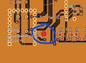 2/ Depending the USB A cable/device the low side switching (GND) may not work. Some devices have shield connected to GND, and shield is connected to PE. Can you prevent a PE loop, and thus no switching on the USB-A connected device ? PE is to GND (gerber). That means that the front USB (pico zero) is not PE protected. Am I wrong ? I would hard connect GND to SHIELD, and high side switch 5V on USB. 3/ when you add a resistor (1.5k) from GP12 to GND (Vmax = 3.6V), you do not need LK1/LK2/LK3. Or 1.2k if you use a shottky diode for D2. These are minor issues though, I love the way you always include a nice user manual with each of your designs. TOP. Volhout P.S. you have PM. Edited 2025-01-16 21:02 by Volhout PicomiteVGA PETSCII ROBOTS |
||||
| Mixtel90 Guru Joined: 05/10/2019 Location: United KingdomPosts: 8911 |
The highlighted screw is very close to the tracks, yes. Agreed that an insulating washer is recommended here. The USB-A socket has a specific use - it feeds a DC motor at 5V for a tiny air pump. It's not intended for anything else. This supply has to be switched as it's timed as part of CO2 dosing. The reasons that it's a USB-A connector are that the pump comes fitted with a moulded USB-A plug and there's no space for anything wider! I don't think I should connect GND to PE as that would short out any EMC capacitor in a SMPS that may be feeding it. I was told that it's not good practice unless you have control of the type of SMPS. On the other hand, touchable metal in the vicinity of the mains conductors should be connected to PE for safety. I can't win. :) There is a PE-connected barrier trace between DC GND (which is floating) and all PCB traces on the mains side, top and bottom of the PCB. Connecting to the USB-C connector is exactly the same as plugging a Pico into a PC. --- The series resistors GP12 and GP13 are simply protection resistors for driving the WS2812B strips. D2 drops the voltage to the strip to the point where the Vin(high) for the data pin comes within the maximum output from the Pico. These strips are designed for 5V so follow the rules for 5V TTL inputs and shouldn't really work properly from 3V3. However, I've had one that didn't work yet. :) The resistors and D2 aren't really needed, but they are cheap. . Edited 2025-01-16 21:36 by Mixtel90 Mick Zilog Inside! nascom.info for Nascom & Gemini Preliminary MMBasic docs & my PCB designs |
||||
| Volhout Guru Joined: 05/03/2018 Location: NetherlandsPosts: 5934 |
Hi Mick, I understand your reasoning on PE. I think it all depends on the 12V power supply you use. If it is a class-II the 12V pins may be floating halfway between L and N (120Vac versus PE) with a high impedance (the Y-caps). You should be able to measure that with a DVM. But in UK you are lucky to have non-reversable wall outlets. A UK typical power supply may be designed to not have this 120Vac. Our Dutch (= German legacy) wall outlets are reversable. Anyway.. you know what you are doing, so I shut up.... Volhout PicomiteVGA PETSCII ROBOTS |
||||
| Mixtel90 Guru Joined: 05/10/2019 Location: United KingdomPosts: 8911 |
No, thanks for your comment. It would be very easy to add an optional link between GND and PE. I think that would be a good idea. As any decent SMPS should easily be able to handle a PE connection on either DC output pole the only question is the cap. TBH I hadn't considered L-N reversal. That would be a "bad thing" in this design anyway as the AC outputs are only single pole switched. Most UK domestic installations link N to PE at the incomer. The L and N then go through RCD protection and any imbalance in the currents trips the RCD. I wonder if a N-E neon to indicate incorrect polarity might be an idea? Not sure where it could go though. --- Edit: Yes, it looks like I can tuck a resistor and wire-ended neon in behind the display. The light from it might just be visible, but a tiny hole in the front panel just above the display might work well as the inside will normally be dark. . Edited 2025-01-17 19:27 by Mixtel90 Mick Zilog Inside! nascom.info for Nascom & Gemini Preliminary MMBasic docs & my PCB designs |
||||
| Mixtel90 Guru Joined: 05/10/2019 Location: United KingdomPosts: 8911 |
A few changes have been made and new PCBs are on order. Now on version 3.1 * More clearance around PCB fixing holes. * DC GND can optionally be linked to PE (only really recommended with linear supplies). * USB supply is now high-level switched. * MOSFETs that might be used for PWM outputs now have series gate resistors to reduce stress on the GPIO pins. * A "wrong polarity" neon has been fitted internally for those countries with reversible mains plugs. If the board is in an enclosure you will probably need a tiny hole above the display to see it. You may have to change RZ to suit your mains supply voltage. * The RTC can now be unplugged even when modified to use the CR2032.  v3.1 circ.pdf Mick Zilog Inside! nascom.info for Nascom & Gemini Preliminary MMBasic docs & my PCB designs |
||||
| Volhout Guru Joined: 05/03/2018 Location: NetherlandsPosts: 5934 |
Hi Mick, I like 3.1. The wrong polarity mains can also be fed to an adc pin (via a 5meg/22k resistor divider) and the zero can show on lcd. Volhout PicomiteVGA PETSCII ROBOTS |
||||
| Mixtel90 Guru Joined: 05/10/2019 Location: United KingdomPosts: 8911 |
As all the pins are used I'd suggest a bit of PCB hacking to get rid of the buzzer. Cut the trace to GP2 (the buzzer) Cut the trace to GP29 (S1) Link S1 to GP2 (to move S1 onto GP2) Use GP29 as the analogue input. I think that could be done quite neatly. The high value resistor could be in a bit of heatshrink underneath the PCB. You will need to link GND to PE for this. An opto-coupler with a capacitive dropper put across the neon might be another way. You can use a digital input then. I wonder if the Pico could detect it capacitively using a few turns of wire round the neon? Mick Zilog Inside! nascom.info for Nascom & Gemini Preliminary MMBasic docs & my PCB designs |
||||
| Volhout Guru Joined: 05/03/2018 Location: NetherlandsPosts: 5934 |
Mick, For my son's frog habitat I need to measure wet bulb humidity/temperature. So I will use SK3 for that. It has 4.4V/GND/ and 2 GPIO's for the 2 DS18B20's. The pullups can be added in the cables. I may even replace D2 to get 3.3V. That frees up GP26 that I can use as an ADC channel (cut LK4). Did you check power consumption (the OLED at 3.3V) and temperature of the linear reg on the ZERO ? I have a 78S05 (switcher that is LM7805 pin compatble) for U1. Volhout Volhout Edited 2025-02-24 20:56 by Volhout PicomiteVGA PETSCII ROBOTS |
||||
| Mixtel90 Guru Joined: 05/10/2019 Location: United KingdomPosts: 8911 |
No, I didn't bother with the display current. I've used them before and not had a problem. It's difficult to measure the reg temperature as it's underneath the module so it's not accessible while the system is running. However, I've used it for hours while developing the software. There's only that, the temperature sensor and the RTC on 3V3. The reg is rated at 500mA and they (rather cleverly I thought) mounted it right underneath the USB connector to get some heatsinking. ----------------- Edit: I've now forced the display on (it's designed to shut off after 2mins normally) and put a bit of black tape on the USB socket (I have a IR thermometer). I'll leave it on for a while and see if there's any meaningful temperature rise. You may be able to replace D2 with a red LED to get a bit of volt drop. There's only a mA or so needed for each sensor. . Edited 2025-02-24 23:02 by Mixtel90 Mick Zilog Inside! nascom.info for Nascom & Gemini Preliminary MMBasic docs & my PCB designs |
||||
| Mixtel90 Guru Joined: 05/10/2019 Location: United KingdomPosts: 8911 |
No worries. The USB socket is less than 1.2C above ambient so the 3V3 reg isn't raising it much. If I try to target at about 1in (the minimum) to vaguely under the PCB the most I can get is about 6C above 20.5C ambient. The RP2040 is under there too so that will be adding a bit of heat. The relays are at about 5C above ambient. It's pointless checking the 5V reg as there are no LED strips on. I expect that to warm up a bit. There are none on because I couldn't put my hands on a big enough 12V supply at the time. :) Mick Zilog Inside! nascom.info for Nascom & Gemini Preliminary MMBasic docs & my PCB designs |
||||
| Mixtel90 Guru Joined: 05/10/2019 Location: United KingdomPosts: 8911 |
I have more mosfets coming from AE. AO3400 (N-channel 98p per hundred) and AO3401 (P-channel £1.15 per hundred). SOT-23 package and these are some serious devices! AO3400 Vds = 30V RDS(on) = <52mΩ (Vgs = 2V5) <33mΩ (Vgs = 4V5) <28mΩ (Vgs = 10V) ID = 5.8A (Vgs = 10V) Pd = 1.4W @ 25°C 1W @ 70°C Vgs(th) = 1V1 RDS(on) = 52mΩ max @ Vgs = 2V5 ID = 4A AO3401 Vds = 30V RDS(on) = <120mΩ (Vgs = 2V5) <65mΩ (Vgs = 4V5) <50mΩ (Vgs = 10V) ID = 4.2A (Vgs = 10V) Pd = 1.4W @ 25°C 1W @ 70°C Vgs(th) = -1 RDS(on) = 120mΩ max @ Vgs = 2V5 ID = 1A I'll be testing these out on the V3.1 board when everything turns up. If I can see them. ;) Mick Zilog Inside! nascom.info for Nascom & Gemini Preliminary MMBasic docs & my PCB designs |
||||
| Mixtel90 Guru Joined: 05/10/2019 Location: United KingdomPosts: 8911 |
I have the boards ready for playing. I'm just wondering whether or not to complete the software on the 3.0 board then strip it and build the 3.1 from that. Software is coming along nicely. I can now write and run lighting control scripts which can be changed easily using EDIT without a lot of messy programming. The system needs polishing yet, but it's virtually there. Here's the updated manual for the Version 3.1 board. manual31.pdf I have a USB isolator on order from ebay. I'm hoping it will make life a lot easier when programming the RP2040-Zero while it's still getting power from a switching supply that puts 90VAC leakage on GND! This isn't a fault, it's normal for switchers. Mick Zilog Inside! nascom.info for Nascom & Gemini Preliminary MMBasic docs & my PCB designs |
||||
| Volhout Guru Joined: 05/03/2018 Location: NetherlandsPosts: 5934 |
Mick, The board arrived in good shape. Unfortunately, the housing I had envisioned is going to work, since you used every square milimeter, also the edges... To be continued... 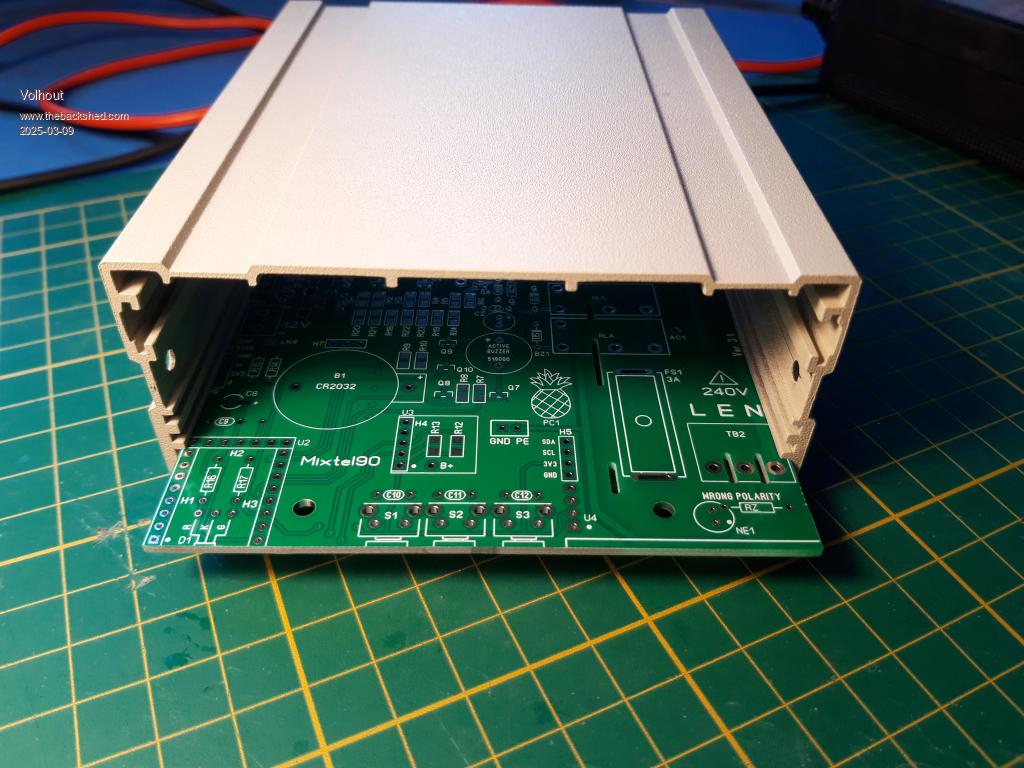 PicomiteVGA PETSCII ROBOTS |
||||
| Volhout Guru Joined: 05/03/2018 Location: NetherlandsPosts: 5934 |
Mick, The board arrived in good shape. Unfortunately, the housing I had envisioned is not going to work, since you used every square milimeter, also the edges... To be continued... PicomiteVGA PETSCII ROBOTS |
||||
| Page 1 of 2 |
|||||
| The Back Shed's forum code is written, and hosted, in Australia. | © JAQ Software 2026 |
