
|
|
Forum Index : Microcontroller and PC projects : Proof of concept - design your own Pico system.
| Author | Message | ||||
| Mixtel90 Guru Joined: 05/10/2019 Location: United KingdomPosts: 8911 |
What it says really - just a proof of concept at the moment. I haven't even thought of a silly name for it yet. :) All errors, spelling mistakes etc. are copyright Mixtel 90. This needs the RM2015M enclosure as the stacked display modules make it too high for the usual one. 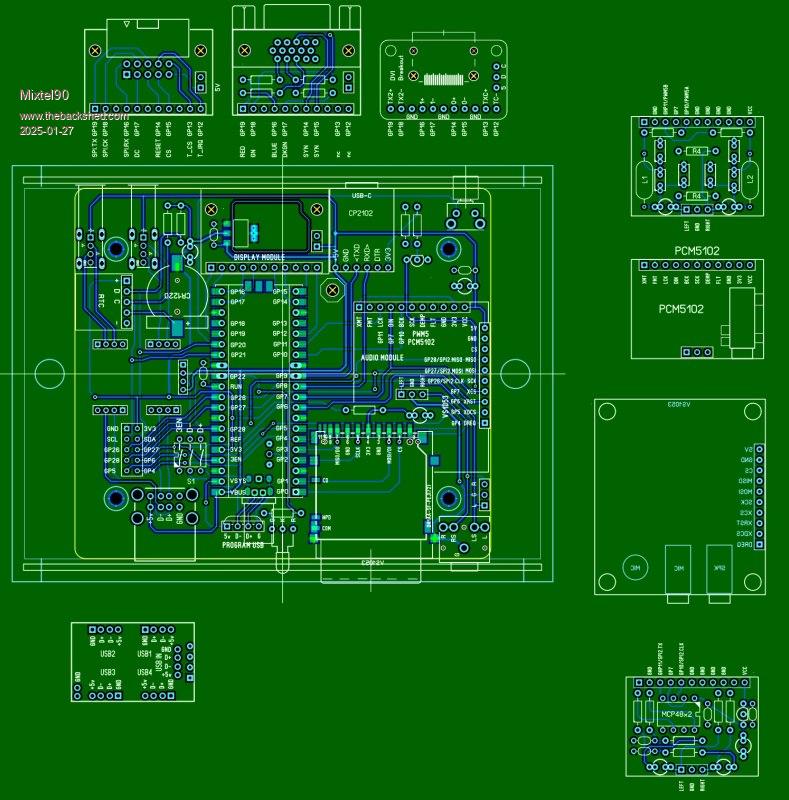 1. Choose your processor You can use either a Raspberry Pi Pico or a Pico 2. The PCB is designed for these only and is unlikely to work with any module that is not 100% compatible both electrically and mechanically. The Pico uses the RP2040. This is the original module. It will not work with the HDMI display under MMBasic. The Pico 2 uses the RP2350A. This will work with all the display modules. 2. Surface mount or plug-in Pico? If surface mounting you will need the vertical USB-C programming connector. There are no jump wires needed for the Pico. You have the advantage of the shortest HDMI connections and most rugged construction. The disadvantage is that it is very difficult to remove the Pico. If making it plug-in you will need to provide the headers and sockets for the Pico. You will need the "mini" micro-USB plug to connect the USB signals to the USB-C programming connector position (which is not fitted). If you want the red heartbeat signal on the front panel you will need a jumper wire connected to the pad beneath the Pico. The plug-in assembly is less rugged and you will have to remove it from the case to update MMBasic (you have to unplug the "mini" connector and plug in the PC lead but there is likely to be insufficient clearance for this). You do have the advantage of an easily upgradable system though. 3. Choose a Display option There are three alternative systems, each requires its own variation of MMBasic: LCD - this is for connecting a SPI display with or without touch support. It uses the SPI (SPI0) port. The connector is a polarised 10-pin box header, suitable for connecting a ribbon cable via a IDC plug. 1 - GND 2 - MISO 3 - DC 4 - CLK 5 - RESET 6 - MOSI 7 - CS 8 - T_IRQ 9 - VCC (5V) 10 - T_CS Example: OPTION SYSTEM SPI, GP18, GP19, GP16 OPTION LCDPANEL ILI9341, L, GP17, GP14, GP15 OPTION TOUCH GP13, GP12 VGA - The standard MMBasic VGA display system. Example: OPTION VGA PINS GP14, GP16 DVI - using a standard HDMI connection. This is not supported on the original RP2040 Pico under MMBasic. OPTION HDMI PINS 13, 14, 16, 19 The display modules plug into the same header that the Adafruit HDMI breakout board uses. The rear end is supported on two insulating pillars. 4 - Choose an Audio system There are four alternative options here: PWM - This uses the filter designed by Volhout. Example: OPTION AUDIO GP10, GP11 SPI DAC - Using the MCP48x2 chip to give 8-bit, 10-bit or 12-bit resolution. Example: OPTION AUDIO SPI GP7, GP10, GP11 VS1053 - This is a hardware CODEC module which also supports MIDI playback. This uses all the spare GPIO pins. If udsing this module you will need to solder wires to the rear of the SPK socket and connect them to the 3-pin header next to the front panel jack socket. Example: OPTION AUDIO VS1053, GP26, GP27, GP28, GP7, GP5, GP4, GP6 I2S DAC - Using a PCM5102 module. This is not supported on the original RP2040 Pico. Example: OPTION AUDIO I2S GP10, GP7 . Edited 2025-01-27 04:30 by Mixtel90 Mick Zilog Inside! nascom.info for Nascom & Gemini Preliminary MMBasic docs & my PCB designs |
||||
| javavi Guru Joined: 01/10/2023 Location: UkrainePosts: 562 |
One HDMI video connector should be made on the main board, and the other two optionally on additional boards. Also, for the VGA video output, you can make a switching scheme for the VGA121/VGA222 palette (there are 8 lines involved anyway).There are many interesting retro emulator projects for this VGA222 circuit. I would also think about how to drag the Pico module to the edge of the board, thereby getting rid of the USB connector for programming and at the same time the heartbeat LED nearby. If you put the Pico module on the connector, there will be space under it for the USB Hub switch |
||||
| Mixtel90 Guru Joined: 05/10/2019 Location: United KingdomPosts: 8911 |
No. :) To do things like that needs a bigger board. Bigger boards cost appreciably more even if they are only slightly bigger than 100x100. There's no point in having both a VGA or LCD on the board as well as HDMI. You can never use HDMI with anything else so it's pointless to make the design more complicated. All three versions need different firmware anyway. There will be no VGA switching unless MMBasic supports it - there's no point as I couldn't support it. I'm not going to learn another language. :) At the moment there is barely 5mm between the "mini" plug and the front panel. If you *do* make the switch accessible as well as the Pico's USB then you have no choice but to connect the usb by wire links to the pads under the Pico - and someone *will* screw things up by plugging something into the USB when they shouldn't i.e. most of the time. It also means a non-standard case and I'm not going that way. I start with an available case and work round that. ----------------- Edit: I just realized. If you wanted 222 VGA all you need is a VGA display module with a different resistor network. You might need to go SMD though, but it's possible. The other 2 pins are there, just not used. Edited 2025-01-27 06:43 by Mixtel90 Mick Zilog Inside! nascom.info for Nascom & Gemini Preliminary MMBasic docs & my PCB designs |
||||
| Volhout Guru Joined: 05/03/2018 Location: NetherlandsPosts: 5934 |
Hi Mick, This would be a good modular board to test out all the varieties of PicoMite, without having to own 12 different designs. It only lacks the PS2 connectors (mouse and keyboard). But honestly, I fail to see the PS2 mouse advantage since large majority of these are ball mice (not optical) and I wonder if you still can find mice that are in good working order. It may also be a good idea remove the linear regulator (jumper disable). The switcher is more efficient, is present, and for non-PWM audio it may not matter. DAC's all have their own internal reference. Regards, Volhout PicomiteVGA PETSCII ROBOTS |
||||
| Mixtel90 Guru Joined: 05/10/2019 Location: United KingdomPosts: 8911 |
Strangely enough, the regulator was a fairly late addition. :) I'm with you though, I'm not sure that it's necessary. The only thing it's used for is to reduce noise on a PWM audio output. I might just get rid of it, it's only something else to go wrong. Of course, if you aren't using the VS1053 it might be possible for someone to connect PS2 stuff to the GPIO pins in some way. You just can't have GP8 and GP9. ------------------------- EDIT I'd just like to point out that I can't develop this to a build yet. It's totally dependent on getting the fixing hole dimensions and positions of the Adafruit DVI breakout module and seeing if they happen to line up with (or be close enough to) those of the VGA socket. They appear to be very close, but until I can get a module I can't tell. They are in pretty short supply in the UK, only Pi Hut appears to have any at all and they only had 17 when I last looked. I have one on order now anyway. Edited 2025-01-27 20:30 by Mixtel90 Mick Zilog Inside! nascom.info for Nascom & Gemini Preliminary MMBasic docs & my PCB designs |
||||
| Volhout Guru Joined: 05/03/2018 Location: NetherlandsPosts: 5934 |
Hi Mick, Might not be a major issue, but on the USB hub that I have here, the distance between USB2 and USB3 is wider than the distance between USB1 and USB4. Something like 1.5mm different. Volhout PicomiteVGA PETSCII ROBOTS |
||||
| Mixtel90 Guru Joined: 05/10/2019 Location: United KingdomPosts: 8911 |
Yeah, they are funny sizes. Don't pay too much attention to the accuracy at this stage - I seem to have picked up the wrong Makro in SL6. I've deleted that one now. :) Fixed. The original makro was a guesstimate as I couldn't find a dimensioned drawing anywhere. The second was produced by putting the module on a piece of paper and using a pin to prick holes in a piece of paper then measuring it! Edited 2025-01-27 21:53 by Mixtel90 Mick Zilog Inside! nascom.info for Nascom & Gemini Preliminary MMBasic docs & my PCB designs |
||||
| Mixtel90 Guru Joined: 05/10/2019 Location: United KingdomPosts: 8911 |
I've just got my DVI breakout board and it looks like things will fit nicely. :) The fixing centres are identical but I have to use M2.5 spacers rather than M3. The VS1053 spacer really needs M3 as M2,5 is rather "sloppy". Incidentally, there is a dimensioned drawing of the DVI board but some essential dimensions are missing. The Eagle file is available but I haven't got that. Mick Zilog Inside! nascom.info for Nascom & Gemini Preliminary MMBasic docs & my PCB designs |
||||
| The Back Shed's forum code is written, and hosted, in Australia. | © JAQ Software 2026 |
