
|
|
Forum Index : Microcontroller and PC projects : Running PIO flat out?
| Page 1 of 2 |
|||||
| Author | Message | ||||
| Bleep Guru Joined: 09/01/2022 Location: United KingdomPosts: 809 |
A question for our resident PIO experts, probably Peter or Harm. I've just splashed out on a second hand 200MHz Oscilloscope and I'm trying to generate a 200MHz signal, or there about to test it with. I have managed to use the Pico SDK to build an executable, which is overclocked to 428MHz toggling a GPIO pin flat out, I get a nice 107MHz signal, which the scope displays fine. (zip file below) Is there a way of getting the PIO under MMBasic to do something similar, preferably higher frequency, closer to 200MHz. Even better a variable frequency, up to as high as possible. I realise the step size is likely to be relatively large, but a selection of test frequencies would be nice? maybe a selection of power of 2 frequencies on adjacent pins? Any thoughts? Thanks in anticipation. :-) Kevin. FastToggle.zip |
||||
| Mixtel90 Guru Joined: 05/10/2019 Location: United KingdomPosts: 8911 |
At full speed a PIO state machine can carry out 1 instruction per CPU clock cycle. I suppose that will mean one instruction to set a pin, one to reset it and one to jump back to the first instruction. That would, I think, give a pin that clocked at a maximum of CLK/3 Hz. 142.66MHz. Now, there are instructions that can actually do two things in one clock cycle (side set etc.). I'm not well up enough on the PIO to be able to help there. It could be that the reset and jump back could be combined. Note. If a state machine hits the end of it's memory area it automatically jumps back to its start point, so if you put the set instruction at the start point and the end instruction as the last instruction in memory it should toggle at CLK/2, I think. . Edited 2025-01-31 01:52 by Mixtel90 Mick Zilog Inside! nascom.info for Nascom & Gemini Preliminary MMBasic docs & my PCB designs |
||||
| Volhout Guru Joined: 05/03/2018 Location: NetherlandsPosts: 5934 |
Hi Kevin, Here you go. This toggles GP0 at half the PIO clock speed. Change the f0 value according your wishes. setpin gp0,PIO1 PIO ASSEMBLE 1,".program toggle" pio assemble 1,".line 0" 'start line 0 PIO ASSEMBLE 1,"set pindirs,1" 'set GPIO to output PIO ASSEMBLE 1,".wrap target" PIO ASSEMBLE 1,"set pins,0" 'set low PIO ASSEMBLE 1,"set pins,1" 'set high PIO ASSEMBLE 1,".wrap" 'wrap back to wrap_target PIO ASSEMBLE 1,".end program list" 'configure pio1 StateMachine 0 f0 = 133e6 '1MHz, change this to meet your need ' a b c d e f g 'a,e=side set c,g=OUT b,f=set p0 = Pio(PINCTRL 0,1,,,,GP0,) e0 = Pio(EXECCTRL GP0,Pio(.wrap target),Pio(.wrap)) 'write the configuration PIO init machine 1,0,f0,p0,e0,,0 'SM0 start at address 0 PIO START 1,0 do:loop Theoretically you can set the PIO clock frequency to the same value as the ARM speed. But if PIO can really do 400MHz I am not sure. Try it. Another problem may be the IO pin that cannot toggle fast enough. At 200MHz, you may see a sine wave half the 3.3V amplitude. Becuase that is all the IO pin silicon can do. Volhout P.S. if you want to use a different GPIO pin, change the GP0 in PINCTRL. The one in EXECCTRL is a dummy, and can stay the same. Edited 2025-01-31 02:14 by Volhout PicomiteVGA PETSCII ROBOTS |
||||
| Mixtel90 Guru Joined: 05/10/2019 Location: United KingdomPosts: 8911 |
Ah, that is the question! Can you get 400MHz out of a component specified at a normal speed of 150MHz? :) Mick Zilog Inside! nascom.info for Nascom & Gemini Preliminary MMBasic docs & my PCB designs |
||||
| Bleep Guru Joined: 09/01/2022 Location: United KingdomPosts: 809 |
Hi Harm, That was quick, I'll give it a go. Thanks very much. :-) Hi Mick, I only need it to do 200Mhz, but even at 107, it's already fairly sinusoidal, so it may/or not cope. Regards Kevin. |
||||
| Mixtel90 Guru Joined: 05/10/2019 Location: United KingdomPosts: 8911 |
Have you set up your probe using the square wave from the scope? Better check it anyway. Also, with those edge times, you need the short GND wire from the probe tip. Edited 2025-01-31 03:01 by Mixtel90 Mick Zilog Inside! nascom.info for Nascom & Gemini Preliminary MMBasic docs & my PCB designs |
||||
| PhenixRising Guru Joined: 07/11/2023 Location: United KingdomPosts: 1961 |
I wonder if a 74HC14 Schmitt-Trigger would help? |
||||
| phil99 Guru Joined: 11/02/2018 Location: AustraliaPosts: 3293 |
It may help, especially if the 74HC14 is close to the Pico. The output resistance of the Pico pins is 40 - 50Ω so driving the scope input capacitance may contribute to the rounding. Edit. An odd thing. Tried the program above but using FIN to show the output (Pico2 VGA beta 5) and the Pico freezes when PIO output is connected to FIN. Unplug the link and it resumes running. Tried various CPU speeds, PIO speeds and FIN sampling times but always same result. > option list PicoMiteVGA MMBasic RP2350A Edition V6.00.02b5 OPTION SYSTEM I2C GP14,GP15 OPTION FLASH SIZE 4194304 OPTION COLOURCODE ON OPTION KEYBOARD US OPTION DEFAULT MODE 3 OPTION DISPLAY 60, 133 OPTION SDCARD GP13, GP10, GP11, GP12 > RUN 0: E081 1: E000 2: E001 0 0 <---------Heartbeat and program stop when GP0 linked to GP7, resume when removed 0 0 0 > > LIST SetPin gp7,FIN,10 SetPin gp0,PIO1 PIO ASSEMBLE 1,".program toggle" PIO assemble 1,".line 0" 'start line 0 PIO ASSEMBLE 1,"set pindirs,1" 'set GPIO to output PIO ASSEMBLE 1,".wrap target" PIO ASSEMBLE 1,"set pins,0" 'set low PIO ASSEMBLE 1,"set pins,1" 'set high PIO ASSEMBLE 1,".wrap" 'wrap back to wrap_target PIO ASSEMBLE 1,".end program list" 'configure pio1 StateMachine 0 f0 = 63e6 '1MHz, change this to meet your need ' a b c d e f g 'a,e=side set c,g=OUT b,f=set p0 = Pio(PINCTRL 0,1,,,,GP0,) e0 = Pio(EXECCTRL GP0,Pio(.wrap target),Pio(.wrap)) 'write the configuration PIO init machine 1,0,f0,p0,e0,,0 'SM0 start at address 0 PIO START 1,0 Do Pause 2000 Print Pin(GP7) Loop > Edit 2 FIN works ok when linked to a PWM pin. Edited 2025-01-31 08:05 by phil99 |
||||
| PhenixRising Guru Joined: 07/11/2023 Location: United KingdomPosts: 1961 |
On the RP2350, GP0 supports the new-ish FFIN What happens if you flip the roles? |
||||
| phil99 Guru Joined: 11/02/2018 Location: AustraliaPosts: 3293 |
Yes, it works with SETPIN GP1,FFIN With CPU and PIO speed 378MHz FFIN reads 189MHz. Edit. I should have read the manual! Edited 2025-01-31 08:37 by phil99 |
||||
| PhenixRising Guru Joined: 07/11/2023 Location: United KingdomPosts: 1961 |
Ah, had it in my head that it was GP0 but I looked at my new board layout and sure-enough, I have it routed to GP1  |
||||
| Bleep Guru Joined: 09/01/2022 Location: United KingdomPosts: 809 |
Hi Harm, Thanks very much for the PIO Frequency test program, I can confirm the PIO on my 2040 will run at full clock frequency at 420MHz. so I have 'Option CPUCLOCK 420000' and 'f0 = 420E6' in the code, which give me this. :-) 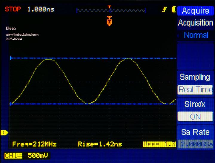 Which is probably not too bad, all things considered. Thanks again. Regards, Kevin. |
||||
| GAVI Newbie Joined: 20/11/2024 Location: ItalyPosts: 13 |
as far as I know the 74HC14 cannot exceed 40 MhZ, but in practice even less. Used as an output buffer for frequency of 100-200 MhZ it would not work at all. |
||||
| Bleep Guru Joined: 09/01/2022 Location: United KingdomPosts: 809 |
Hi Harm or Peter, I've been experimenting with the PIO and Assembler. Just because it looked like I could and I have a 4 channel scope, I wanted to modify your original code to now toggle 5 GPIO pins simultaniously, along with another 5 GPIO pins as Side Set, but out of phase. I was originaly using the old assembler, but it looked as though there had been problems with compiling SideSet with that, so I've now swapped the the latest B11 and the new assembler. This code was also to test the various drive strengths and speed settings, to see if there was a noticeable difference. I have managed to get the 5 consecutive pins GPIO0 to GPIO4 all toggeling together, but have completely failed to get GPIO5 to GPIO9 to toggle using Side Set. Any sugestions appreciated. :-) Regards Kevin. ' Toggle multiple GPIO with set and out of phase with Side Set. SetPin gp0,PIO1 SetPin gp1,PIO1 SetPin gp2,PIO1 SetPin gp3,PIO1 SetPin gp4,PIO1 SetPin gp5,PIO1 SetPin gp6,PIO1 SetPin gp7,PIO1 SetPin gp8,PIO1 SetPin gp9,PIO1 PIO ASSEMBLE 1 .program multi_toggle .side set 5 ' pinsdir, &b11111 '5 side set pins .line 0 ' start line 0 Set pindirs, &b11111 'set GPIO 0to4 to output" .wrap target Set pins,&b00000 side &b11111 'set low, side set high Set pins,&b11111 side &b00000 'set high, side set low .wrap 'wrap back to wrap_target .end program list 'configure pio1 StateMachine 0 f0 = 210e6 '100MHz, change this to meet your need ' a b c d e f g 'a,e=side set c,g=OUT b,f=set p0 = Pio(PINCTRL 5,5,,,GP5,GP0,) e0 = Pio(EXECCTRL GP0,Pio(.wrap target),Pio(.wrap)) 'write the configuration PIO init machine 1,0,f0,p0,e0,,0 'SM0 start at address 0 PIO START 1,0 Timer =0 Dim Integer count=0 Print "Frequency =" f0/2000000"MHz" Do If Timer > 999 Then Timer =0:Inc count Select Case count Case 30 Poke word &H4001c004,&H00 Inc count Print "2mA, normal" Case 40 Poke word &H4001c004,&H01 Inc count Print "2mA, Hi speed" Case 50 Poke word &H4001c004,&H10 Inc count Print "4mA, normal" Case 60 Poke word &H4001c004,&H11 Inc count Print "4mA, Hi speed" Case 70 Poke word &H4001c004,&H20 Inc count Print "8mA, normal" Case 80 Poke word &H4001c004,&H21 Inc count Print "8mA, Hi speed" Case 90 Poke word &H4001c004,&H30 Inc count Print "12mA, normal" Case 100 Poke word &H4001c004,&H31 Inc count Print "12mA, Hi speed" Case 110 Poke word &H4001c004,&H21 Inc count Print "Standard, 8mA, Hi speed" End Select Loop |
||||
| Volhout Guru Joined: 05/03/2018 Location: NetherlandsPosts: 5934 |
Your proble. Is that gpio 5..9 are not set as output. In the new assembler Peter has added a funtion that automatically sets pins defined in pinctrl, as output. Very handy in your case. You have to look for details in the 6.00.02 beta thread. It is invoked by adding some additional ,1,1,1 to one of the pio commands. You could also remove the set pindirs. Volhout PicomiteVGA PETSCII ROBOTS |
||||
| Bleep Guru Joined: 09/01/2022 Location: United KingdomPosts: 809 |
Hi Harm or Peter, I've spent all day trying to get this working, I've read and Re-read the Beta 02 thread. Just to be quite sure, this is on a RP2040, running latest B11. If I remove the "Set pindirs, &b11111" I get no GPIO toggeling at all, so for the moment I'm leaving that in. I've reduced the side set to only toggle 1 GPIO, just to make it simpler. Reading the Beta 02 tread, it appears I need to set a bit at the end of the "Pio(EXECCTRL GP0,Pio(.wrap target),Pio(.wrap),0,1)" to enable Side set?, but this appears to do nothing? If I add the opt command ".side set 1 opt" I no longer get a square wave out from the GPIO0 to GPIO5 being driven with "Set pins" I now get a pulse every fifth clock, so a 20MHz pulse, So I have no idea what that is actually doing? again I have removed it. So I'm back to where I was, I have got all 5 "Set Pins" GPIO0 to GPIO5 toggeling, giving a reasonable square wave at 100MHZ, but I cannot get any life out of the side set pin or pins? Any help appreciated. Regards, Kevin. ' Toggle multiple 2040 GPIO with set and out of phase with Side Set. SetPin gp0,PIO1 SetPin gp1,PIO1 SetPin gp2,PIO1 SetPin gp3,PIO1 SetPin gp4,PIO1 SetPin gp5,PIO1 SetPin gp6,PIO1 SetPin gp7,PIO1 SetPin gp8,PIO1 SetPin gp9,PIO1 PIO ASSEMBLE 1 .program multi_toggle .side set 1 ' opt ' pinsdir, &b11111 '1 side set pins .line 0 ' start line 0 Set pindirs, &b11111 'set GPIO 0to4 to output" .wrap target Set pins, &b00000 side 1 'set low, side set high Set pins, &b11111 side 0 'set high, side set low .wrap 'wrap back to wrap_target .end program list 'configure pio1 StateMachine 0 f0 = 210e6 '100MHz, change this to meet your need ' a b c d e f g 'a,e=side set c,g=OUT b,f=set p0 = Pio(PINCTRL 1,5,,,GP5,GP0,) e0 = Pio(EXECCTRL GP0,Pio(.wrap target),Pio(.wrap),0,1) 'write the configuration PIO init machine 1,0,f0,p0,e0,,0 'SM0 start at address 0 PIO START 1,0 Timer =0 Dim Integer count=0 Print "Frequency =" f0/2000000"MHz" Do If Timer > 999 Then Timer =0:Inc count Select Case count Case 30 Poke word &H4001c004,&H00 Inc count Print "2mA, normal" Case 40 Poke word &H4001c004,&H01 Inc count Print "2mA, Hi speed" Case 50 Poke word &H4001c004,&H10 Inc count Print "4mA, normal" Case 60 Poke word &H4001c004,&H11 Inc count Print "4mA, Hi speed" Case 70 Poke word &H4001c004,&H20 Inc count Print "8mA, normal" Case 80 Poke word &H4001c004,&H21 Inc count Print "8mA, Hi speed" Case 90 Poke word &H4001c004,&H30 Inc count Print "12mA, normal" Case 100 Poke word &H4001c004,&H31 Inc count Print "12mA, Hi speed" Case 110 Poke word &H4001c004,&H21 Inc count Print "Standard, 8mA, Hi speed" End Select Loop Edited 2025-02-22 03:55 by Bleep |
||||
| matherp Guru Joined: 11/12/2012 Location: United KingdomPosts: 11521 |
opt uses one of the five bits available to delay and/or side_set. You can't have 5 side_set and opt. Try with just 4 |
||||
| Bleep Guru Joined: 09/01/2022 Location: United KingdomPosts: 809 |
I was only using 1 side set bit at the time, I seem to remember if I tried nto use 5 and put the "opt" in it would not compile with an error. I don't want to use "opt", it was just an experiment. Edited 2025-02-22 05:11 by Bleep |
||||
| matherp Guru Joined: 11/12/2012 Location: United KingdomPosts: 11521 |
PIO INIT MACHINE PIO%, stateMACHINE%, clockspeed [,pinctrl] [,execctrl] [,shiftctrl] [,startinstruction] [,sideout [,setout] [,outout] sideout, setout, and outout can be set to 0 (default) or 1 to specify if pins defined in pinctrl should be INITialised as inputs (0) or outputs (1) |
||||
| Bleep Guru Joined: 09/01/2022 Location: United KingdomPosts: 809 |
Ah ok thanks Peter, I'll give that a try and report back. |
||||
| Page 1 of 2 |
|||||
| The Back Shed's forum code is written, and hosted, in Australia. | © JAQ Software 2026 |
