
|
|
Forum Index : Microcontroller and PC projects : PicoMite based electronic console
| Page 1 of 2 |
|||||
| Author | Message | ||||
| dddns Guru Joined: 20/09/2024 Location: GermanyPosts: 874 |
Hello! I finished my project and would like to share some pictures. Only some polishing is left to do but it works already very nice. I don't want to fish for compliments but maybe give some inspirations for the interested. Have fun 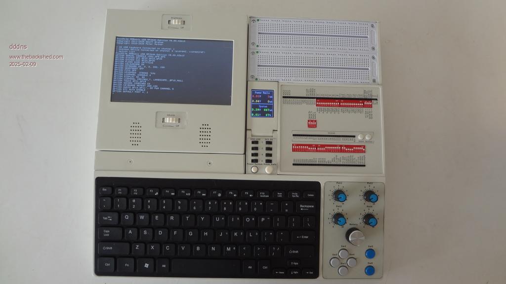 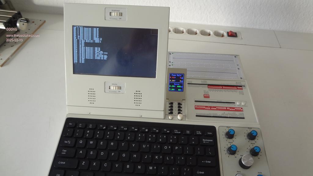 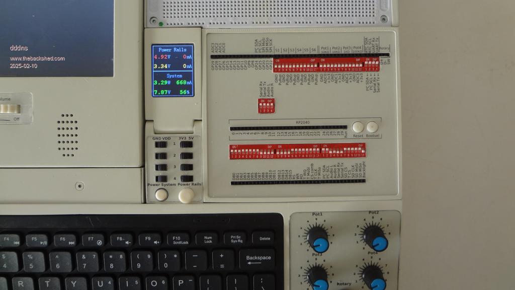 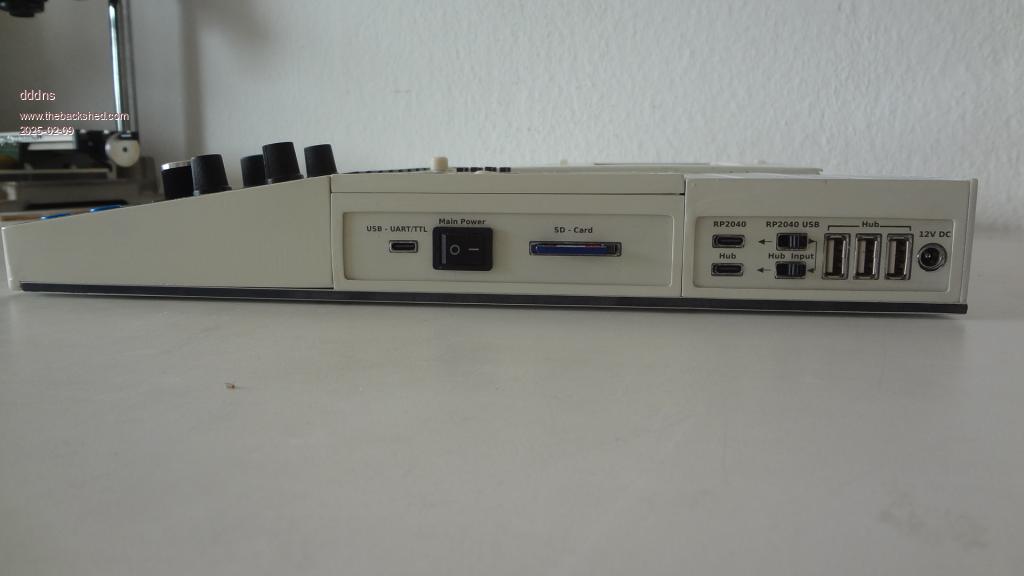 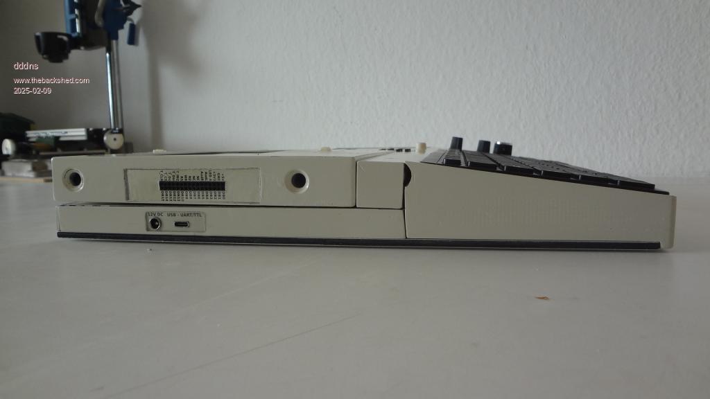 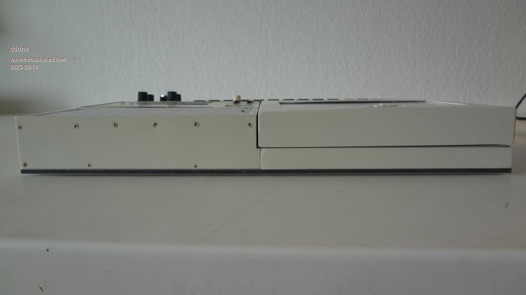 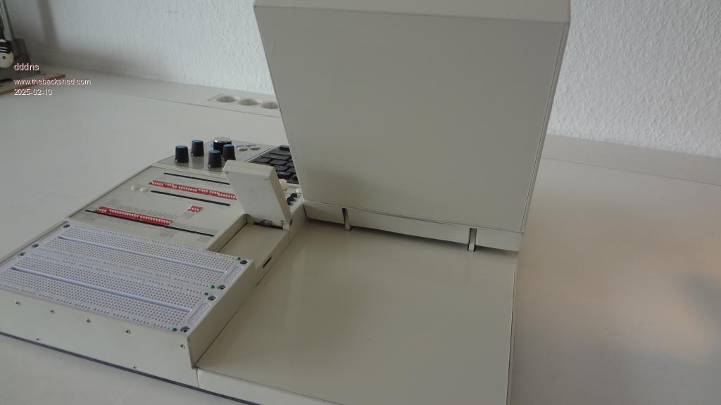 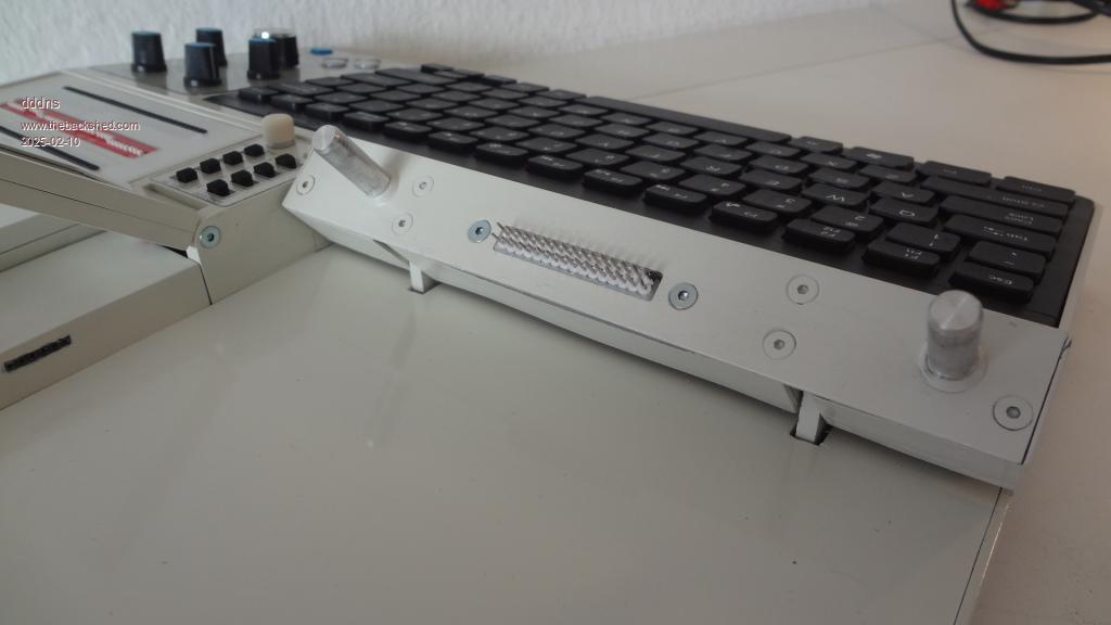 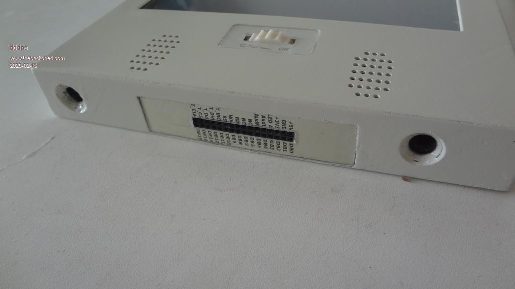 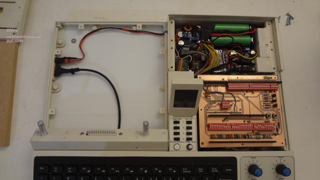   Edited 2025-02-10 00:14 by dddns |
||||
| Amnesie Guru Joined: 30/06/2020 Location: GermanyPosts: 763 |
Hi, Impressive work of detail, I really like it! Especially the breadboard area is cool, I have something similar in mind but not this big as yours. Cool to see some actual projects. For what are all those red DIP switches? Greetings Daniel Edited 2025-02-10 00:11 by Amnesie |
||||
| lizby Guru Joined: 17/05/2016 Location: United StatesPosts: 3811 |
Quite masterful. Amazing amount of work goes into a product as finished as this is. PicoMite, Armmite F4, SensorKits, MMBasic Hardware, Games, etc. on FOTS |
||||
| Volhout Guru Joined: 05/03/2018 Location: NetherlandsPosts: 5994 |
Hi dddns, Looks very rugged and is beautiful painted. As an experimenters tool, you can't wish for any better. How many pico's are in there ? 1 for development, and 1 driving the screen (some sort of terminal)? Beautiful... Volhout Edited 2025-02-10 01:26 by Volhout PicomiteVGA PETSCII ROBOTS |
||||
| PeteCotton Guru Joined: 13/08/2020 Location: CanadaPosts: 645 |
Absolutely fantastic work on every level! That's inspiring.  |
||||
| stanleyella Guru Joined: 25/06/2022 Location: United KingdomPosts: 2807 |
lot of work, looks brill. |
||||
| dddns Guru Joined: 20/09/2024 Location: GermanyPosts: 874 |
Thanks to everybody. Each pin of the builtin peripherals goes to the outlet and is then connected to the builtin pico through the switches. So the pico and/or the peripherals can be used separately if the according switches are off. You can have as well your own pin assignment by interconnecting the according sockets with jump wires. The power monitor is driven by an Atmel328p, the display is the 128x160 St7735 Edited 2025-02-10 04:45 by dddns |
||||
| Mixtel90 Guru Joined: 05/10/2019 Location: United KingdomPosts: 8964 |
Lovely job! :) Mick Zilog Inside! nascom.info for Nascom & Gemini Preliminary MMBasic docs & my PCB designs |
||||
Grogster Admin Group Joined: 31/12/2012 Location: New ZealandPosts: 9995 |
Thing of beauty. Excellent work. Looks very professional indeed. Smoke makes things work. When the smoke gets out, it stops! |
||||
| PhenixRising Guru Joined: 07/11/2023 Location: United KingdomPosts: 2003 |
 |
||||
| Frank N. Furter Guru Joined: 28/05/2012 Location: GermanyPosts: 1143 |
Wow, very cool!!! Frank |
||||
| tritonium Newbie Joined: 16/06/2018 Location: United KingdomPosts: 24 |
Hi Nicely thought out and engineered. I'm intrigued about what exactly is in the main display screen module. It seems to be mountable in both landscape and portrait. My guess is 7 inch? touch screen- but how is it driven? The screen connector seems to have touch signals and a 16 bit i/o bus, along with led and power. Dave |
||||
| dddns Guru Joined: 20/09/2024 Location: GermanyPosts: 874 |
Thanks. The display module consists out of a ssd1963 7" 800x480 touch lcd, a 3W amp and two speakers and it will have its own pwm controller for the backlight. It is mountable in portrait and landscape or usable stand alone. it was below 40€ at the time i bought it. It can be used in 8 or 16bit mode. So when configured in 8bit mode, there are 8 free GPs including all 4 ADCs. That why i have choosen to implement a second dip switchable pin config to free the ADCs which is regarding GP8 - GP11 and GP26-GP29. |
||||
| PeteCotton Guru Joined: 13/08/2020 Location: CanadaPosts: 645 |
It looks like a metal case. Did you make that yourself? If so, how? It looks beautiful. |
||||
| dddns Guru Joined: 20/09/2024 Location: GermanyPosts: 874 |
Everything is done by me at home. The body is made out of printed ABS/ASA parts. The base plate, the backcover of the display and the cover for the space beneath the display is a compound Alu/Platics material in 4 and 2mm, normally used for e.g. traffic signs and ideal for painting them after. All plastics are sanded, then a plastics primer and then paint from the car paint area. |
||||
| dddns Guru Joined: 20/09/2024 Location: GermanyPosts: 874 |
Just Printing parts often lacks on preciseness. That is why i had to rework many parts on a small desktop mill. Like all the label printings are covered by acrylic glass. In order to make them fit and look nicely it needs to be within a tolerance of +-0,1 mm max. So the main hardware tools i used were a 3D printer, a small cnc mill and a lathe. Otherwise a stand drill, akku drill and of cause a "Dremel" :)) The softwrae i used was freecad, kicad, inkscape, pcb2gcode(GUI), candle2 repetierhost and the arduino environment ..and of cause Linux Edited 2025-02-11 07:04 by dddns |
||||
| PeteCotton Guru Joined: 13/08/2020 Location: CanadaPosts: 645 |
Thanks! You've done an amazing job. |
||||
| Malibu Senior Member Joined: 07/07/2018 Location: AustraliaPosts: 261 |
Saying that it looks 'pretty special' is an understatement! Really nicely done John |
||||
| ebbandflow Regular Member Joined: 31/08/2023 Location: United StatesPosts: 53 |
Um, this is outright gorgeous!!  The amount of effort you've invested is obvious and inspiring. Thank you for sharing. |
||||
| zeitfest Guru Joined: 31/07/2019 Location: AustraliaPosts: 691 |
Very nice ! so good, I thought it was a factory-made casing |
||||
| Page 1 of 2 |
|||||
| The Back Shed's forum code is written, and hosted, in Australia. | © JAQ Software 2026 |
