
|
|
Forum Index : Microcontroller and PC projects : PicoMite HDMI/USB Problem
| Author | Message | ||||
| ehewlett Newbie Joined: 14/02/2025 Location: CanadaPosts: 9 |
Hello! I'm an enthusiastic amateur at using microcontrollers, having played mostly with the Pi Pico (and now the Pico 2), and an almost complete noob at soldering. I did manage to get an original PicoMite (VGA/PS2) fully soldered and assembled and up and running, which I documented here, but, given the inconveniences of working with VGA and PS2, I was delighted to see the updated PicoMite HDMI/USB design, and ordered myself a couple of boards to try to get one of those up and running. I've fully documented that process here, but I've now run into a roadblock that's beyond my ability to figure out. Basically, the HDMI connection works, but, even after typing the configuration command, "OPTION RESET HDMIUSB", via a serial connection without the jumper pins in place, and then putting the jumper pins in place, USB keyboards don't work - there doesn't even seem to be any power to the USB ports. Here's a photo of my setup: 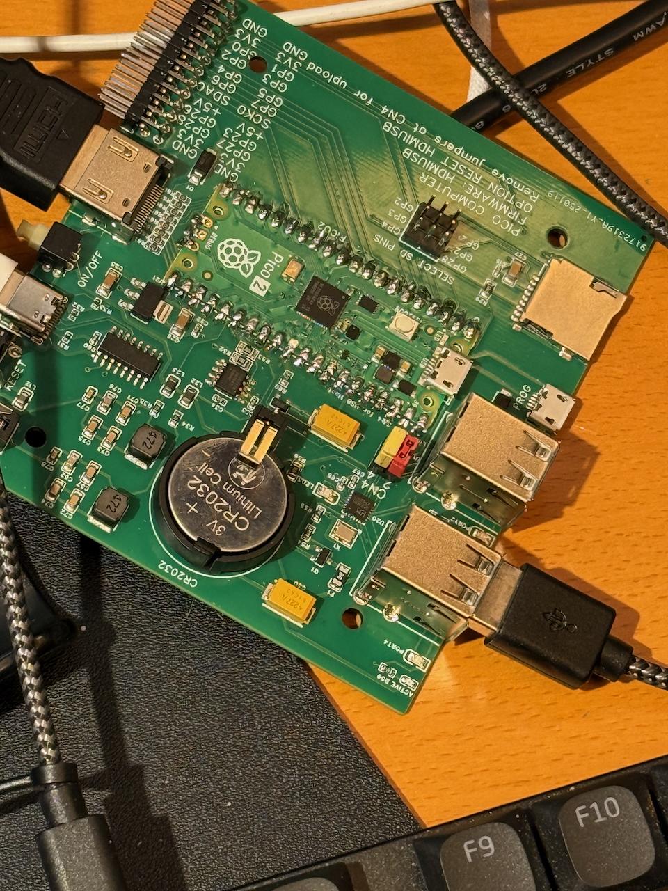 I also don't seem to be able to re-flash the Pi Pico 2. When I remove the jumpers and hold down the "BOOTSEL" button on the Pico 2 and connect via USB, the Pico 2 does not show up like a drive, like it's supposed to. I wonder whether the two problems may be connected, but, given my inexperience, I'm at a loss at this point, and hoping that someone here may be able to suggest what may have gone wrong, or at least some avenues of exploration that I should be considering to figure out what may have gone wrong! Thanks in advance for any assistance any of you may be able to provide! |
||||
| George H Newbie Joined: 03/07/2020 Location: United StatesPosts: 33 |
Make sure you solder through the three holes on the back of the board. It can be difficult to get the solder all the way through them. One of these provides power to the USB system. I had trouble until I squeezed the Pico tight against the board with one hand and reflowed the solder on the back with the other. On one of my boards I cut short pieces of wire from a resistor and fed it into the holes, soldered and trimmed. Seemed to work pretty well. Using liquid flux in the holes should help the solder flow in. -George |
||||
| JohnS Guru Joined: 18/11/2011 Location: United KingdomPosts: 4336 |
Are there some places to check voltages to see if USB ought to work or to figure what may be wrong? Er, if a DVOM (multi-meter) is available! John |
||||
| ehewlett Newbie Joined: 14/02/2025 Location: CanadaPosts: 9 |
Thank you! Thank you! Thank you, George! I did wonder if something like this might be the problem. Squeezing the Pico tight against the board with one hand and reflowing the solder with the other (pressing down on the tip of the soldering iron as I did so to ensure that the melted solder would flow deeper into the hole) did the trick! I now have a fully functional PicoMite 2! So exiting! |
||||
| ehewlett Newbie Joined: 14/02/2025 Location: CanadaPosts: 9 |
Thanks, John. As an electronics hardware noob, I might have a multimeter somewhere (I think I bought one some time ago), but I don't really know how to use one. Thankfully George's simple tip did the trick! I was at least able to determine that no power was flowing out through the USB ports via the simple expedient of plugging various USB devices into them and noting that none of them seemed to be receiving power, but I'm sure a multimeter would have been handy (if I knew how to use it properly) for tracking down exactly where current *wasn't* flowing... |
||||
| phil99 Guru Joined: 11/02/2018 Location: AustraliaPosts: 3293 |
Refer to the pin diagram in the manual, "Hardware Details" chapter. The pins to measure on the Pico are near the red and yellow jumpers. Pin 40 - VBUS = about 5V (typically 4.8 to 5.2) Pin 39 - VSYS = about 0.2V less than VBUS Pin 36 - 3V3 = 3.3V Black probe to any GND. |
||||
| JohnS Guru Joined: 18/11/2011 Location: United KingdomPosts: 4336 |
It's great it's working. Find the meter and use it a bit (with a working battery in it!). There will be lessons online (but probably start with resistors if you have some and move on to low voltages). It can be handy to at least be able to check power (5V or 3V3) is there and an output port is high or low when you think you've told it to be. edit: phil99 beat me to it John (pretty useless with hardware but not entirely so) Edited 2025-02-18 07:13 by JohnS |
||||
| The Back Shed's forum code is written, and hosted, in Australia. | © JAQ Software 2026 |
