
|
|
Forum Index : Microcontroller and PC projects : RP2350B now in stock at JLC so....
| Page 1 of 2 |
|||||
| Author | Message | ||||
| matherp Guru Joined: 11/12/2012 Location: United KingdomPosts: 11519 |
Before incorporating into more complex boards I thought it would make sense to do something to prove the design first. I'm using some different techniques from the Pico design guide but I think/hope they are better and should be more stable (overclockable). Not routed yet but would this be a useful form factor? Ignore the fact the headers are showing upside down. 64-pin 1" between rows Schematic d353f280-63c2-4015-99ec-9071e3be392d.pdf 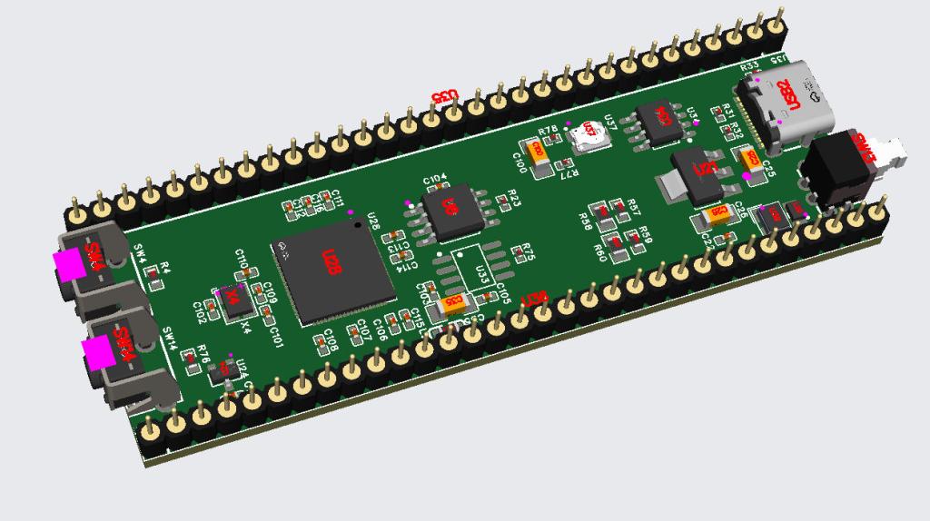 |
||||
| PhenixRising Guru Joined: 07/11/2023 Location: United KingdomPosts: 1961 |
Looks perfect. The problem with the other boards is that they are populated with features that I have no use for.  |
||||
| Mixtel90 Guru Joined: 05/10/2019 Location: United KingdomPosts: 8911 |
That's very nice indeed. I can see it being popular. :) Mick Zilog Inside! nascom.info for Nascom & Gemini Preliminary MMBasic docs & my PCB designs |
||||
| gadgetjack Senior Member Joined: 15/07/2016 Location: United StatesPosts: 233 |
I like it a lot!! Watching for the next move.... |
||||
| phil99 Guru Joined: 11/02/2018 Location: AustraliaPosts: 3293 |
Yes, more practical layout than the PGA2350. Perfect for embedded controllers. If higher overclocking than the PGA2350 is possible then even more useful. |
||||
Grogster Admin Group Joined: 31/12/2012 Location: New ZealandPosts: 9975 |
Nice one, my son! U33? I2C EEPROM footprint? RTC? EDIT: Sorry - asked before I looked at the schematic - PSRAM chip. Edited 2025-02-21 15:15 by Grogster Smoke makes things work. When the smoke gets out, it stops! |
||||
| WhiteWizzard Guru Joined: 05/04/2013 Location: United KingdomPosts: 2991 |
Looking good there - I like your circuit around U34 and i reckon you’re onto something there regarding it making a big difference to ‘stability’. Watching with great interest. FYI - I have a very stable ‘complete setup’ based around the RP2350B XL Stamp exposing all GPIOs. Proof of concept built on stripboard and using multiple break-out modules. Your module here would be perfect to replace the XL Stamp…. |
||||
| matherp Guru Joined: 11/12/2012 Location: United KingdomPosts: 11519 |
Here is the routed layout. Now I just need to persuade JLC to build it. At the moment they require you to use a specific crystal and inductor to meet the Raspberry Pi design guide but I don't want to do it that way. Worst case I will have to put them on the board unwired  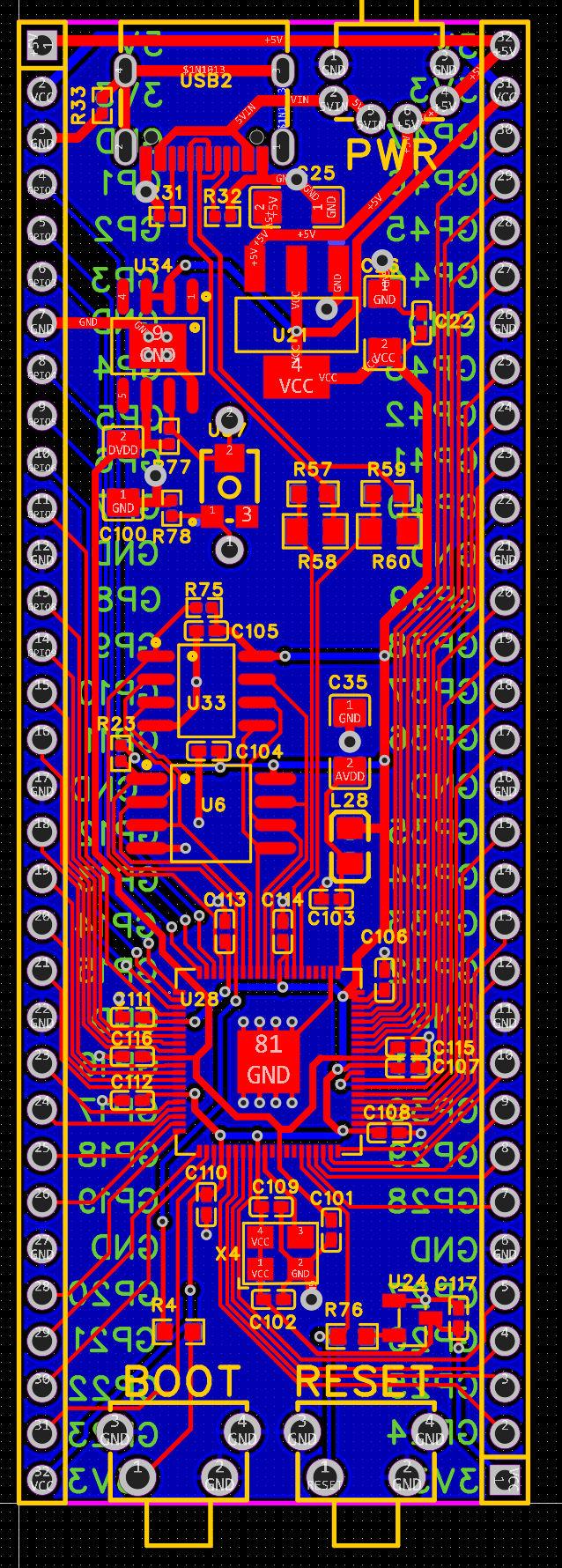 |
||||
| PhenixRising Guru Joined: 07/11/2023 Location: United KingdomPosts: 1961 |
WTF. The reason that they are in this PCB business is for people to design new/better solutions. |
||||
| circuit Guru Joined: 10/01/2016 Location: United KingdomPosts: 305 |
Oh my gosh! Thank you. This is precisely the board that I suggested here:RP2350 Development Board - like the MX795 Sparkfun board. My dream board comes true! -I am really hoping that JLC will produce this board complete with crystal and inductor. I am really excited about this project! |
||||
| George H Newbie Joined: 03/07/2020 Location: United StatesPosts: 33 |
Yes!!!!! |
||||
| matherp Guru Joined: 11/12/2012 Location: United KingdomPosts: 11519 |
Here is the final version - now includes a heartbeat LED. I've ordered 5 so hopefully no errors. JLC don't have stock of the PSRAM chip (APS6404L-3SQR-SN) so I've ordered those separately. SOP8 so easy enough to hand solder. The two test points allow you to measure and set the variable resistor which controls the DVDD voltage. Set to 0 for 1V, 12.1K for 1.2V, 30.3K for 1.5V and if you really want to cook the chip 48.6K for 1.8V. Schematic 840789ca-5e7c-4f8a-ae25-f99c024b7f84.pdf 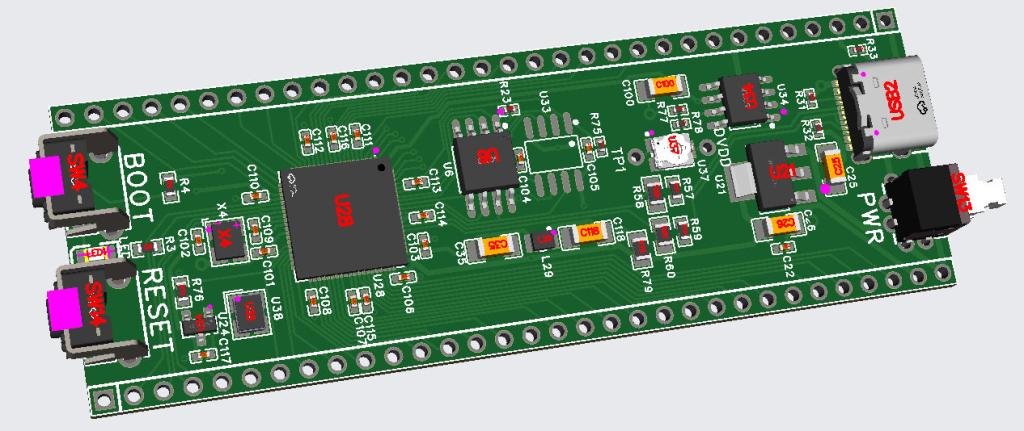 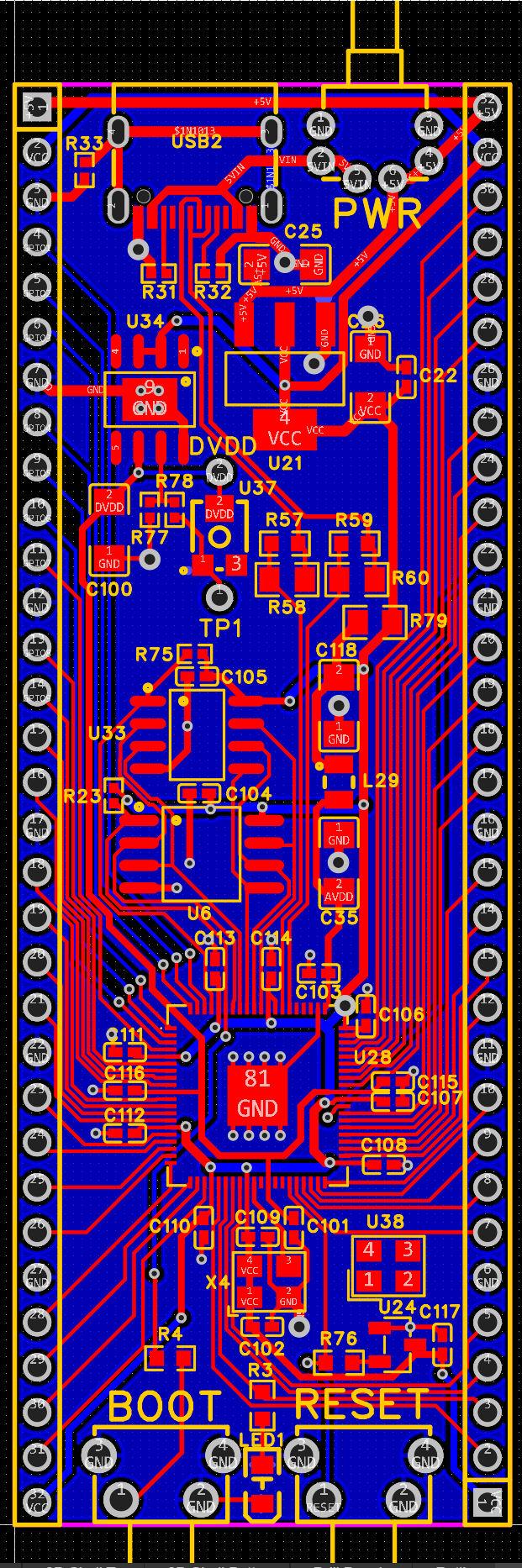 Edited 2025-02-22 04:53 by matherp |
||||
| dddns Guru Joined: 20/09/2024 Location: GermanyPosts: 846 |
Very nice design to me and I would buy it! Maybe i cannot find them but i miss pinouts for reset and bootsel. And it would be nice to make the psram cs configurable through solder pads or so. Edited 2025-02-22 07:51 by dddns |
||||
| phil99 Guru Joined: 11/02/2018 Location: AustraliaPosts: 3293 |
Perhaps solder wires to the underside of the switches, or if using external switches replace the switches on the board with pins. |
||||
| WhiteWizzard Guru Joined: 05/04/2013 Location: United KingdomPosts: 2991 |
@Peter, Just querying the pot position to drive DVDD. According to the datasheet, your max voltage out is 1v. Should it be alongside R77 as opposed to R78? Vout= 0.5x(R77/R78) Just checking Edited 2025-02-22 19:35 by WhiteWizzard |
||||
| matherp Guru Joined: 11/12/2012 Location: United KingdomPosts: 11519 |
Think its correct. R78 is R2, R77+U37 is R1 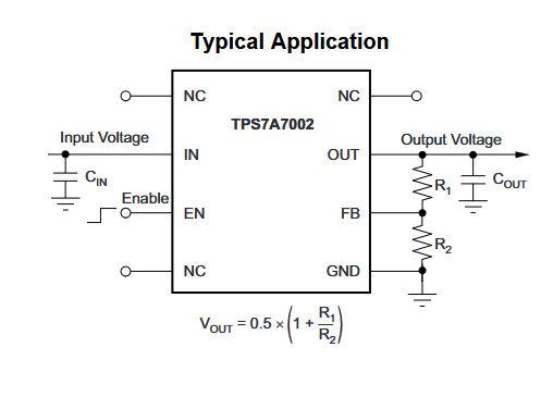 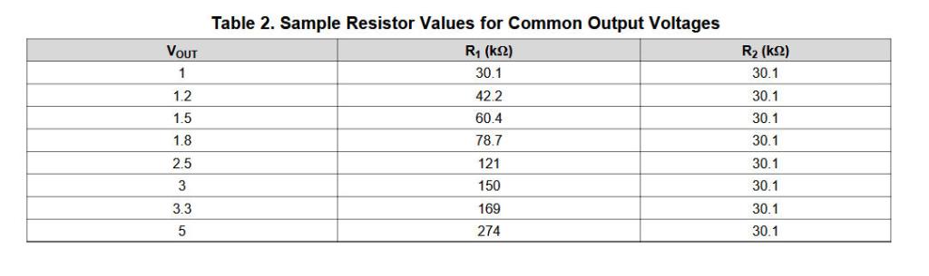 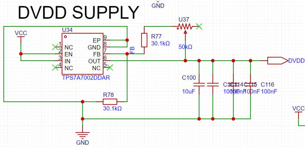 |
||||
| Mixtel90 Guru Joined: 05/10/2019 Location: United KingdomPosts: 8911 |
It allows a deal of healthy over-volting. :) 1V to around 1V8 when the spec says 1V21 absolute max. I won't argue with that. They are allowing for 85C case temperature. :) Mick Zilog Inside! nascom.info for Nascom & Gemini Preliminary MMBasic docs & my PCB designs |
||||
| phil99 Guru Joined: 11/02/2018 Location: AustraliaPosts: 3293 |
A minor refinement may be to tie the free end of the trimmer to the wiper. In the event of the wiper contact point going open it will limit the voltage to 1.8V. As it is now it will try to rise to Vin. I don't know how fussy the regulator is to the value of the lower leg resistor but if the trimmer were in that leg the output would drop if the trimmer went open. |
||||
| WhiteWizzard Guru Joined: 05/04/2013 Location: United KingdomPosts: 2991 |
Yes, this is correct (I was purely going on your pdf schematic that show R77 by itself (and the pot with R78). Do you have an ETA for your first batch? I know many people here will be very interested in your RP2350B module…. |
||||
| Mixtel90 Guru Joined: 05/10/2019 Location: United KingdomPosts: 8911 |
Both good points. R2 should be kept between 27K and 33K according to the spec. Mick Zilog Inside! nascom.info for Nascom & Gemini Preliminary MMBasic docs & my PCB designs |
||||
| Page 1 of 2 |
|||||
| The Back Shed's forum code is written, and hosted, in Australia. | © JAQ Software 2026 |
