
|
|
Forum Index : Microcontroller and PC projects : PicoMite: High-side switch - Help needed
| Author | Message | ||||
| WhiteWizzard Guru Joined: 05/04/2013 Location: United KingdomPosts: 2991 |
I am reaching out to everyone to ask for their thoughts/experience about a high-side switch. I am simply wanting to switch the 5V rail that supplies a PicoMite based circuit) from a GPIO pin on a secondary (totally separate) Pico. Googling seems to show one common way of doing it is by using an NPN to drive the gate of a P-channel mosfet. Seen lots of theoretical circuits, however, there are many P-channels out there and the ‘parameters’ need to be carefully selected. Ultimately the Pico circuit I wish to control will draw no more than 1amp (with all peripheral components) so was looking at specifying it to switch a minimum of 2amps. I do not want to use a mechanical relay, and also do not want to switch GND; and hence am asking if anyone can help in specifying components they have successfully used to switch 5V from a GPIO pin. I am open to ICs too as opposed to transistors - but ideally any that have been reliably used rather than just ‘theory’. Edited 2025-02-24 19:35 by WhiteWizzard |
||||
disco4now Guru Joined: 18/12/2014 Location: AustraliaPosts: 1127 |
Soft Power On/Off on FotS This I think was written by CaptainBoing so should be good. It came from the origin FotS. F4 H7FotSF4xGT |
||||
| WhiteWizzard Guru Joined: 05/04/2013 Location: United KingdomPosts: 2991 |
Thanks for that link. Exactly the circuit I’ve been seeing; and here it is nice to see some actual specific transistors. |
||||
| CaptainBoing Guru Joined: 07/09/2016 Location: United KingdomPosts: 2171 |
HSS can be constructed from any flavour of power MOSFET but N-types need a bit of support "fluff" to boot-strap them into working in an odd manner. P-types seem almost custom made for the task. Price-wise, the N-type + support costs (in components and PCB real estate) just didn't weigh-off against simply using a P-type, so I took a long look at suitable P-type devices. A major consideration was that I didn't want the bulk of a heat-sink if I could avoid it, so... for up to a few amps, NDP6020P is a nice choice - dead cheap and robust. RDSon might be a little high for very high current projects (0.08Ω @12A) = ~320mW @2A. for more power, consider FQP47P06 with RDSon of just a measly 0.026Ω at 24A(!) ~100mW @2A. As you are pumping the gate with a tiddly NPN transistor with a commoned emitter from VIN, you won't have trouble taking the gate more-negative than VIN so none of the VgsTh concerns should find purchase upon your furrowed brow  for the 6020, you could even drive it direct from a GPIO pin as it is 1V max for VGSth, I think you could probably end up with just the MOSFET if you are brutal  ... literally connect the gate to a o/c DOUT with a 4K7 pull-up (need to over-come the gate capacitance fairly quickly) and drive it LO, the thing will turn on. Really, as both sides are well understood, I would consider this - A two component solution! I can already hear the gnashing of teeth from other shedders ... literally connect the gate to a o/c DOUT with a 4K7 pull-up (need to over-come the gate capacitance fairly quickly) and drive it LO, the thing will turn on. Really, as both sides are well understood, I would consider this - A two component solution! I can already hear the gnashing of teeth from other shedders  h Edited 2025-02-25 02:58 by CaptainBoing |
||||
| WhiteWizzard Guru Joined: 05/04/2013 Location: United KingdomPosts: 2991 |
Thanks CaptainBoing. I am totally useless at ‘analogue’ theory so can I be a PITA and ask you if there are any resistor values that need consideration in the aforementioned schematic based on your recommended P-Channel mosfet; and also any consideration to the specific NPN? Ideally want to order some bits within next 24 hours so I can jump straight into a working circuit. Thanks for any further guidance….. |
||||
| CaptainBoing Guru Joined: 07/09/2016 Location: United KingdomPosts: 2171 |
this isn't really analogue, you are simply slamming the MOSFET to the opposing ends of its transconductance zone... it is literally going from a couple of GΩ to a few mΩ as quickly as possible. MOSFETS are brillieant devices and I use them a lot. There is one major consideration which requires more attention than most others: They can get hot if they are switched slowly. If IDS goes from 0A to 20A, somewhere in that switch (it isn't really resistance but ignore that for the illustration), you go to almost zero resistance which means the thing dissipates no power, but it has to go through, say 1Ω at which point it would be dissipating 20W. Now, if you are running the thing without a heatsink, you want to get through that zone as fast as possible. Continuous current in the right place is less of a concern than current switched slowly... The problem with MOSFETs is the gate can have a really high capacitance - maybe a few nF and that takes time to discharge/charge... that makes the clean on-off switch more of a slope and places the MOSFET at greater risk of "staying in the zone" longer. At the levels you have indicated, the 6020 is going to work nicely. A quick gate pull up is required... 4K7 tied to 5V gives you a current of 1mA so using the electrical principals staple of 1CRsec to 63%, that should pull the 1.6nF of the gate HI in about 7uS and 5CRSec for 99% in 35uS - plenty. components for 2A (using that circuit): R1=4K7 (assuming pull up to 5V) R2=10K Q1=NDP6020P Q2=BC107( ) or any other signal NPN you have tons ofC1=omit unless the environment is noisy GPIO pin to POWERON should not be OC - it needs to drive HI and LO for Q2 to saturate nicely knock it up on breadboard and enjoy P.S. my stock list shows that I should have a couple of dozen 6020s on hand so if you have any difficulties finding them ping me a PM and I'll bung some in an envelope for you. hth h Edited 2025-02-25 03:38 by CaptainBoing |
||||
| WhiteWizzard Guru Joined: 05/04/2013 Location: United KingdomPosts: 2991 |
Ok, this is all making sense - Thanks. I have seen people mention using an IRLML6401 MOSFET when doing similar for an Arduino driven hss. Because I have these parts at hand, along with lots of BC548 NPNs; do you see any issues with using these in your circuit (keeping the 4K7 and 10K too)? |
||||
| Volhout Guru Joined: 05/03/2018 Location: NetherlandsPosts: 5931 |
Hi White Wizzard, IRLML6401 is fine in this circuit. Even 3.3V will drive the FET well, and allow for 3A or greater currents, and 5V allows 4A. Since the maximum voltage is 12V, do not use it above. But your application is 5V as I understand. Volhout PicomiteVGA PETSCII ROBOTS |
||||
| CaptainBoing Guru Joined: 07/09/2016 Location: United KingdomPosts: 2171 |
looks a good mix |
||||
| PhenixRising Guru Joined: 07/11/2023 Location: United KingdomPosts: 1961 |
Related information Also this Edited 2025-02-25 17:25 by PhenixRising |
||||
| apalert Regular Member Joined: 06/07/2023 Location: AustraliaPosts: 47 |
NDP6020P seems hard to get, some sites say it's obsolete. I've used the FotS circuit quite a few times substituting PMOS DMG2305UX-7. |
||||
| Volhout Guru Joined: 05/03/2018 Location: NetherlandsPosts: 5931 |
A nice logic level Pchannel FET for the 5V 1A current: AO3401 You can't get much cheaper. 0.060 ohm. $0.016 each including shipping.  Mick pointed me to this device. Used in his Fish Tank Controller. Datasheet Volhout Edited 2025-07-13 16:41 by Volhout PicomiteVGA PETSCII ROBOTS |
||||
| apalert Regular Member Joined: 06/07/2023 Location: AustraliaPosts: 47 |
I've read an opinion elsewhere that to get really snappy switching with a PMOS the pull-up resistor should be in the range of 100R - 1K. I initially used 10K as per the original design on my pico project and was having trouble with a slow shutdown. It seemed the pico was going through a "brownout" stage, lots of garbage appeared on the console and sometimes OPTION AUTORUN got wiped out. Changed to 1k and I think my problems have gone away. I'll live with the 3 - 4 mA cost of that. I've connected the PMOS gate directly to a pico DOUT pin as suggested earlier. However seems problematic attempting to turn the PMOS off by driving the pico output high. Maybe the pico running at 3.3V can't push the gate high enough, especially if the 3 NiMH cells are fully charged. So, to turn the PMOS on (with pin 5 in my case) I use: SETPIN 5, DOUT = 0 Then to turn it off I use: SETPIN 5, OFF Edited 2025-08-07 20:00 by apalert |
||||
| Mixtel90 Guru Joined: 05/10/2019 Location: United KingdomPosts: 8911 |
A mosfet is basically a capacitor, so the faster you can charge and discharge it the better really. However the gate is an extremely high resistance and is, to all intents and purposes, purely voltage driven. For a high side driver I'd try the above mosfet or the DMG2305UX-7, which has an even lower voltage drop. You should be fine with 10K up to the + rail to turn them off - you might be able to go as high as 100K. I'd use a little N-channel mosfet as the driver, something like the 2N7000 as you don't need a base resistor when driving them from the Pico in most cases. The power dissipation is the voltage drop multiplied by the current, so there is a lot of advantage in getting the lowest drop possible. For most loads power is only really dissipated during switching. Look at the data sheet to find the safe operating area graph. That will show you how much current you can get. You will find the maximum drain current for a given gate voltage on another graph. Mick Zilog Inside! nascom.info for Nascom & Gemini Preliminary MMBasic docs & my PCB designs |
||||
| apalert Regular Member Joined: 06/07/2023 Location: AustraliaPosts: 47 |
Thanks Mick, in fact I am using DMG2305UX-7 But I have 2 test circuits, one on a breadboard using DMG2305UX-7 I purchased from Digikey. The other test circuit is on a PCB made and assembled for me by PCBWay and that's the one I have been having the switching speed drama with. Maybe they used an inferior substitute? Mal |
||||
| Mixtel90 Guru Joined: 05/10/2019 Location: United KingdomPosts: 8911 |
It's possible, I suppose. You might have been unlucky and got one from a dodgy batch. The turn on speed should be very fast as there's nothing to limit the gate current (unless you put a resistor in there). If you are seeing slow turn-off then either the gate is taking too long to discharge or perhaps the driver transistor is still passing some current. The gate capacitance on that mosfet isn't all that high really at about 800pF. The threshold voltage is only 0.9V at maximum though, so any leakage through the driver would be significant. In either case, reducing the gate-source resistor should fix it. :) Mick Zilog Inside! nascom.info for Nascom & Gemini Preliminary MMBasic docs & my PCB designs |
||||
| phil99 Guru Joined: 11/02/2018 Location: AustraliaPosts: 3293 |
For faster switching use an active pullup to switch the P-channel MOSFET off. 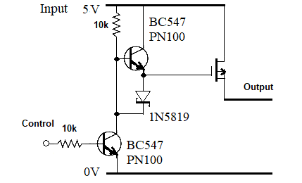 Edit. I messed up the MOSFET symbol but you get the idea. Edited 2025-08-07 22:49 by phil99 |
||||
| Mixtel90 Guru Joined: 05/10/2019 Location: United KingdomPosts: 8911 |
Good idea, especially for a bigger mosfet. A bit of overkill for 800pF of gate capacitance though IMHO. :) Mick Zilog Inside! nascom.info for Nascom & Gemini Preliminary MMBasic docs & my PCB designs |
||||
| The Back Shed's forum code is written, and hosted, in Australia. | © JAQ Software 2026 |
