
|
|
Forum Index : Microcontroller and PC projects : PicoMite HDMI/USB USB Hub Issues
| Page 1 of 4 |
|||||
| Author | Message | ||||
| birefringence Newbie Joined: 25/02/2025 Location: GermanyPosts: 23 |
I have received my ordered PicoMite HDMI/USB boards, soldered a Pico 2 onto one of them and everything seems to be working, except for the USB host ports. At first, I thought my problem could be similar to the one described in this thread https://www.thebackshed.com/forum/ViewTopic.php?FID=16&TID=17703 , but now I don't think it is the same. I tried to follow the instructions, the HDMI output works, I can see the prompt on the screen, I can access the serial console over the USB-C connector and successfully run the OPTION RESET HDMIUSB on it, the PROG port works fine for flashing, and the SD card can be accessed. The USB ports for connecting peripherals, however, do not power on even when the jumpers are placed on CN4. The ACTIVE LED in the corner is the only one that lights up on the board. None of the LEDs related to the USB hub controller turn on. I've measured the correct 3.3V and 5V voltages on the nearest resistors / capacitors to the CH334F, but the PWREN# pin does not go low. Since according to the schematics, the same connections is used for the PROG port and USB host, I assume that I can exclude the possibility that there is a problem with the solder connection through the holes on the backside. I have now run out of ideas what to try next. Does anyone have any suggestions? |
||||
| Frank N. Furter Guru Joined: 28/05/2012 Location: GermanyPosts: 1102 |
Are you sure that you have taken the correct .UF2 file? Can you post which board you have exactly??? Frank |
||||
| matherp Guru Joined: 11/12/2012 Location: United KingdomPosts: 11516 |
With the board powered and no USB devices plugged in what LEDs are lit? You should have the red active LED and the green LED3. Make sure the links between 1 to 2 and 3 to 4 are good and the right way round. Post a picture of the board. If active and LED3 are OK then try plugging in a known good simple keyboard. You do have a good powered supply via the USB-C connector? There have been issues with poor quality cables and/or a weak power source. Check the orientation of LED3 if not lit - if this is wrong this would cause the issue. With a multimeter in diode mode LED3 should light with the multimeter positive lead at the R56 end. If all that is OK, check the orientation of X1 and if necessary use a heat gun to reflow U20. |
||||
| stanleyella Guru Joined: 25/06/2022 Location: United KingdomPosts: 2807 |
5V is needed on VBUS pin 40 to power pico and usb device. I take 5V from usb to ttl converter connected to pc. |
||||
| birefringence Newbie Joined: 25/02/2025 Location: GermanyPosts: 23 |
Thank you for all of the replies! Here are the answers to the questions: 1) Which firmware have I used exactly: PicoMiteHDMIUSBV6.00.01.uf2 2) Which board do I have exactly: 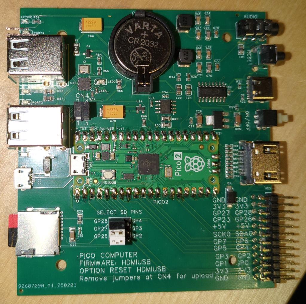 3) Which LEDs are lit: Only the red "active" LED, but NOT the green LED3 4) Check orientation of LED3: Seems correct, it lights up with multimeter in diode mode and positive lead at R56 end. 5) Check orientation of X1: Does this look correct? 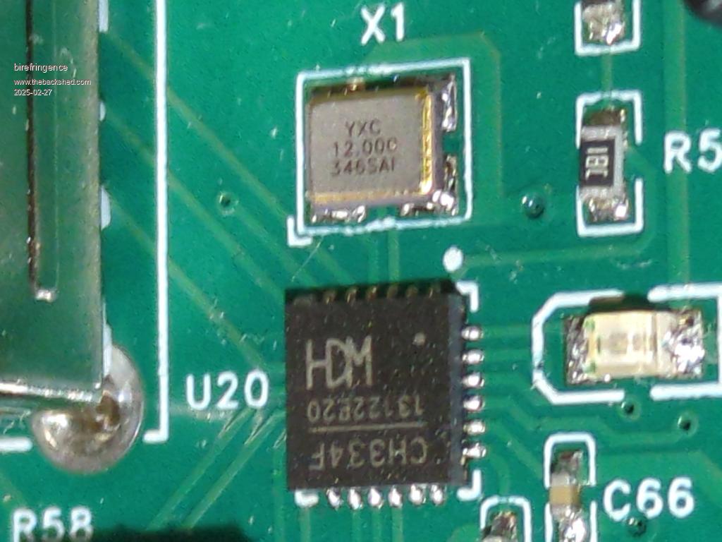 6) Reflow U20: I will first have to borrow a heat gun for this step. 7) USB-C: I have tried three different power sources and cables, all with the same result. |
||||
| birefringence Newbie Joined: 25/02/2025 Location: GermanyPosts: 23 |
I have measured 5V on C79 vs. GND and on R56 vs. GND so I'm quite sure they are available. |
||||
| matherp Guru Joined: 11/12/2012 Location: United KingdomPosts: 11516 |
I can simulate your issue by removing the link between 1 and 2 but leaving 3 and 4 in place. I would check the wiring of that line (replace the jumper) and re-do the soldering of the bottom through hole just to be sure. 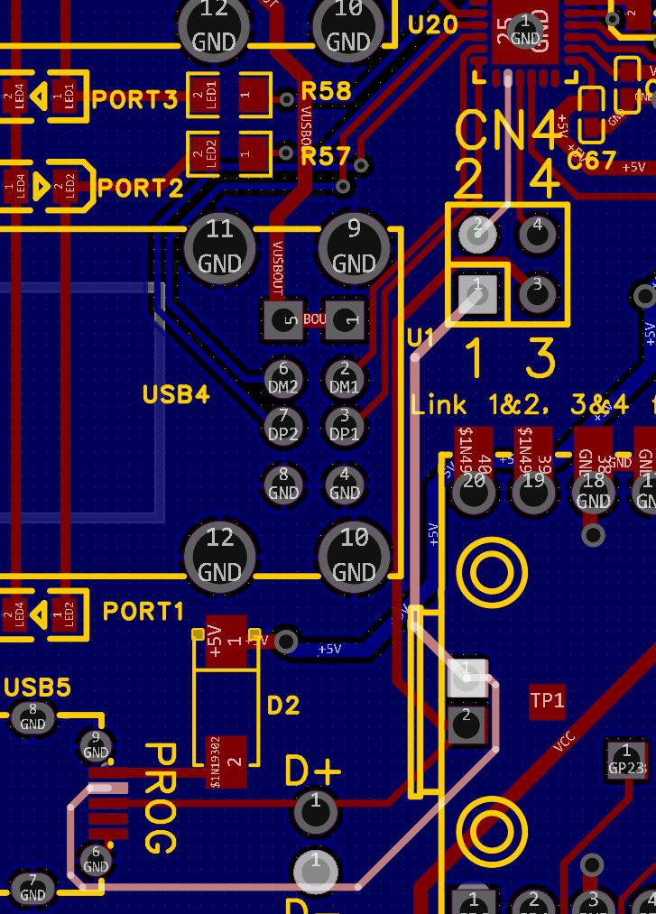 |
||||
| birefringence Newbie Joined: 25/02/2025 Location: GermanyPosts: 23 |
Thank you very much for the suggestions! I tried them, but no success. I also used the multimeter as a continuity tester and checked that there is a connection from the USB port pins directly on the Pico 2 board to the corresponding pins on U20. So it very much looks like the connections are fine. Also, I have borrowed a hot air gun now, but this is a general purpose one that is not specifically made for electronics work, so I'm afraid that it will do more harm than good if I were to use it on the board. I have one more Pico 2 and four more boards, so I may try the whole thing again. However, I would obviously like to avoid the situation were I have attached all my Picos to non-functional boards  Edited 2025-02-28 01:25 by birefringence |
||||
| Mixtel90 Guru Joined: 05/10/2019 Location: United KingdomPosts: 8911 |
If you do *anything* with SMD or heatshrink tube or acrylic sheet/rod it's worth getting a cheap Chinese heat gun. If you do, first open it up and make sure that they connected the earth wire and that it is actually connected to the earth pin of the mains plug! They can be a bit casual about such things sometimes. :) Less than £30 including postage from ebay. Of course, there are better ones for more money, but these are sufficient for occasional use. One of those tools that you wonder how you managed without. If you are going to use hot air to rework the chip then I'd recommend covering the surrounding components with aluminium foil, possibly held in place with some kapton tape. You don't want to risk melting anything and it can be embarrassing if your bits fall off. :( Edited 2025-02-28 02:36 by Mixtel90 Mick Zilog Inside! nascom.info for Nascom & Gemini Preliminary MMBasic docs & my PCB designs |
||||
| stanleyella Guru Joined: 25/06/2022 Location: United KingdomPosts: 2807 |
don't the bits bet glued on first so they don't move? never tried surface mount.. but how hard can it be? .. not :) |
||||
| Mixtel90 Guru Joined: 05/10/2019 Location: United KingdomPosts: 8911 |
Depends. Some solder paste is easily sticky enough to hold the components - even quite large chips. Many chips have a heat transfer pad under them too, which may or may not have something on it. Surface mount difficult? It all depends. I can solder 0805 components without a lot of difficulty. I'm getting better at HDMI connectors. The pads of a RP2040 or RP2350 are far too close for me though. I've been considering getting a 100mm square hotplate for SMD work. Get one of the little SMD soldering kits off ebay or AE. They are very cheap and you get some practice using different components. You need solder paste too, really. And a flux pen and solder wick for when it goes wrong. :) Mick Zilog Inside! nascom.info for Nascom & Gemini Preliminary MMBasic docs & my PCB designs |
||||
| birefringence Newbie Joined: 25/02/2025 Location: GermanyPosts: 23 |
OK, before I try anything more involved, just one more thing: If I connect the PROG port (with jumpers at CN4 removed) to an external powered USB hub, should that work? (it does not seem to be the case) |
||||
| birefringence Newbie Joined: 25/02/2025 Location: GermanyPosts: 23 |
Since I'm still somewhat intimidated by the thought of trying any SMD reworking, I now soldered my second Pico 2 on another board from the batch from JLCPCB. But no luck, it has exactly the same issue. Also, I noticed that LED3 actually does light up a little bit (on both boards) but it is extremely dim. I verified some more connections to U20 and they seem fine (I wasn't able to contact X1 with the tips of my multimeter, though). Edited 2025-03-01 07:53 by birefringence |
||||
| Mixtel90 Guru Joined: 05/10/2019 Location: United KingdomPosts: 8911 |
This is getting a bit silly, isn't it? Let's take it from the top. :) You can load MMBasic. That requires the initial connection to be via the Pico's USB system and the only access is via the USB-C socket on the PCB so that system must be ok. The USB system on the Pico gets switched into Host mode by the HDMIUSB firmware. Once it's in Host mode you lose that connection and your only access is via the 115200 baud console connection. We now know that's working because you've set the OPTIONS. Does OPTION LIST show that the firmware is the HDMIUSB version? If it does I'd be tempted to try a new download and reinstall it from scratch, I think. Looking at the photo of X1 I'm not absolutely certain. Has it got a dot or other indication on the package that's aligned with the orientation mark on the pcb? It's not all that clear (to me anyway) and the dot might be at the opposite corner. I haven't got one of these boards so I've nothing to compare. Mick Zilog Inside! nascom.info for Nascom & Gemini Preliminary MMBasic docs & my PCB designs |
||||
| Sasquatch Guru Joined: 08/05/2020 Location: United StatesPosts: 385 |
The markings and orientation of U20 and X1 match my working boards although the batch/date number are slightly different. Not sure what to think about all this. I think the main bases have been covered, power supply, firmware version, solder connections etc. I built 4 of these boards and shipped one to a fellow shedder who soldered his own Pico2 module. Other than a bit of extra care soldering the backside connections it was very straightforward. Either JLC has got a bad batch of parts, or there must be something different about your setup that you haven't discovered yet? -Carl |
||||
| JohnS Guru Joined: 18/11/2011 Location: United KingdomPosts: 4335 |
Probably a dumb question (sorry), but why is LED3 dim? John |
||||
| Mixtel90 Guru Joined: 05/10/2019 Location: United KingdomPosts: 8911 |
It could just be the chip. It pulls PWREN# low to power up the ports, but the LED is only passing about 1mA even when it's on. You might see a few uA leakage if you look carefully. There must not be enough voltage across R56 to turn Q1 on though. Or maybe there is and F1 is open circuit? The output wouldn't have C80 to stabilise it. I don't know if that's a requirement to stop oscillation, which could show as a dim LED. It would be an idea to check the fuse anyway. If it's open circuit it would also be an idea to look for a possible cause. Mick Zilog Inside! nascom.info for Nascom & Gemini Preliminary MMBasic docs & my PCB designs |
||||
| matherp Guru Joined: 11/12/2012 Location: United KingdomPosts: 11516 |
Just to get rid of the obvious. You are removing the micro-usb connection? You should NEVER have that plugged in when the links 1-2 and 3-4 are in place. |
||||
| birefringence Newbie Joined: 25/02/2025 Location: GermanyPosts: 23 |
Yep, I'm removing the micro USB. When the board is powered, I cannot measure any voltage drop across R56. There is no voltage drop across F1 and I don't measure any resistance across it when the board is powered off, so I think the fuse is fine. I have reflashed multiple times. > option list PicoMiteHDMI MMBasic USB RP2350A Edition V6.00.01 OPTION SERIAL CONSOLE COM2,GP8,GP9 OPTION SYSTEM I2C GP20,GP21 OPTION FLASH SIZE 4194304 OPTION COLOURCODE ON OPTION KEYBOARD US OPTION CPUSPEED (KHz) 315000 OPTION SDCARD GP22, GP26, GP27, GP28 OPTION AUDIO GP10,GP11', ON PWM CHANNEL 5 OPTION RTC AUTO ENABLE OPTION MODBUFF ENABLE 192 OPTION PLATFORM HDMIUSB |
||||
| birefringence Newbie Joined: 25/02/2025 Location: GermanyPosts: 23 |
Thank you very much for all of the feedback! I very much appreciate that! Coming back to this question: Should this work, or will D2 prevent the hub detecting the board as an upstream USB port? It guess I'm very close to ordering one of those cheap hot air guns from eBay ... (and face the challenge of sourcing suitable replacement parts if required). |
||||
| Page 1 of 4 |
|||||
| The Back Shed's forum code is written, and hosted, in Australia. | © JAQ Software 2026 |
