
|
|
Forum Index : Microcontroller and PC projects : ESP-01 Module on CMM2 G2
| Author | Message | ||||
| ManiB Senior Member Joined: 12/10/2019 Location: GermanyPosts: 141 |
The Colour Maximite 2 User Manual describes on page 10: "ESP-01 Module There is a footprint on the PCB for connecting an ESP-01 WiFi module to COM2. Version 5.07.00 and later of the firmware allows COM2 to be used as a serial console so if the correct USB/UART code is loaded into the ESP-01 it will be possible to access the console of the CMM2 remotely. At this time MMBasic does not include any Internet functions using this device in but communications can be established using the normal serial communications protocol included in MMBasic" What is not mentioned, however, is what exactly this “correct USB/UART code” means. Probably another topic that I should actually know about, but unfortunately I don't have a clue again. Searching the forum for the keyword ESP-01 also brought some interesting posts to light (1 or 2), but it didn't help me. Can anyone tell me which USB/UART code I need to copy to the ESP-01 WiFi module? I have ordered this module including programmer: ESP-01 Prog WiFi Programmer Many thanks in advance. Edited 2025-03-05 08:26 by ManiB |
||||
| ManiB Senior Member Joined: 12/10/2019 Location: GermanyPosts: 141 |
Grok Ai says (I will check this out...): To make the ESP-01 WiFi module work with the Colour Maximite 2 (CMM2) Gen 2 as described in the user manual, you need to configure the ESP-01 to act as a transparent serial-to-WiFi bridge. This allows the CMM2's COM2 serial port to communicate wirelessly, effectively providing remote access to the CMM2's console. The manual refers to the "correct USB/UART code" as the firmware that enables this functionality on the ESP-01. While it doesn’t specify the exact firmware, this typically means loading the ESP-01 with a version of the **AT firmware** (provided by Espressif, the maker of the ESP8266 chip inside the ESP-01) or a custom firmware that supports a transparent UART-to-WiFi bridge mode. Since you’ve ordered an ESP-01 module with a programmer (the ESP-01 Prog WiFi Programmer), you’re well-equipped to flash the necessary firmware. Below, I’ll explain what this “correct USB/UART code” likely entails, how to identify and obtain it, and how to set it up for your CMM2 G2. --- ### Understanding the "Correct USB/UART Code" The ESP-01 is based on the ESP8266 microcontroller, which is typically shipped with Espressif’s AT command firmware. This firmware allows the module to interpret AT commands sent over a serial connection (UART) and perform WiFi-related tasks, such as connecting to a network or acting as a serial-to-WiFi bridge. The CMM2 manual’s mention of “USB/UART code” suggests firmware that: 1. Interfaces with the CMM2’s COM2 serial port (UART) via the ESP-01’s TX and RX pins. 2. Enables wireless communication (WiFi) to relay the serial data to a remote device (e.g., a computer or terminal). 3. Supports a transparent bridge mode, where serial data is passed directly to/from the WiFi connection without additional processing. The most straightforward solution is to use the **Espressif AT firmware**, which is widely available and well-documented. This firmware supports AT commands like `AT+CIPMODE` and `AT+CIPSERVER` to set up a transparent bridge or TCP server, which aligns with the CMM2’s requirement for serial console access over WiFi. --- ### Recommended Firmware: Espressif AT Firmware The AT firmware is the de facto standard for using the ESP-01 as a serial-to-WiFi adapter. Here’s why it’s likely the “correct” choice: - **Compatibility**: It works out of the box with serial communication protocols, which MMBasic on the CMM2 supports. - **Transparent Mode**: Using AT commands, you can configure the ESP-01 to pass serial data directly to a WiFi connection. - **Community Support**: It’s widely used, with plenty of documentation and examples. The latest stable version of the AT firmware for the ESP-01 as of early 2025 would be something like **ESP8266 AT Firmware v2.x.x** (e.g., v2.2.1.0 or later). However, the ESP-01 typically has either 512KB or 1MB of flash memory (depending on the model), and older versions (e.g., v1.7.4) are often recommended for compatibility with smaller flash sizes. --- ### Steps to Install and Configure the ESP-01 #### 1. Verify Your ESP-01 Hardware - Check the flash memory size of your ESP-01 module (black PCB = 1MB, blue PCB = 512KB). This affects which firmware version you can use. - Your programmer (ESP-01 Prog with CH340G) is perfect for flashing firmware, as it simplifies the USB-to-UART connection. #### 2. Obtain the Firmware - **Source**: Download the official ESP8266 AT firmware from Espressif’s GitHub repository or website: - Go to [ESP-AT Releases on GitHub](https://github.com/espressif/esp-at/releases). - Look for a version compatible with your ESP-01’s flash size (e.g., “ESP8266_NONOS_SDK” or a precompiled AT firmware binary like `esp-at.bin`). - For a 1MB ESP-01, v2.2.1.0 is a good choice; for 512KB, v1.7.4 is safer. - **Alternative**: Websites like the ESP8266 Community Forum or third-party vendors sometimes bundle firmware with flashing tools. #### 3. Flash the Firmware Using your ESP-01 Prog programmer: - **Tools Needed**: - **ESP Flash Download Tool**: Available from Espressif [here](https://www.espressif.com/en/support/download/other-tools). Use version 3.9.x or later. - Drivers for CH340G (if not already installed on your computer). - **Steps**: 1. Connect the ESP-01 to the programmer (ensure proper alignment: VCC to 3.3V, GND to GND, TX to RX, RX to TX). 2. Set the programmer switch to “PROG” mode (for flashing). 3. Open the ESP Flash Download Tool. 4. Load the firmware binary files (e.g., `boot_v1.x.bin`, `esp-at.bin`, etc.) at the correct memory addresses (typically provided in the firmware documentation, like `0x00000` for bootloader and `0x01000` for the main AT binary). 5. Set the flash settings: - Flash Mode: DIO or DOUT (check your ESP-01’s spec). - Flash Size: 1MB or 512KB (match your module). - Baud Rate: Start with 115200. 6. Click “START” to flash the firmware. 7. Once complete, switch the programmer to “UART” mode and reset the ESP-01. #### 4. Test the Firmware - Use a serial terminal (e.g., PuTTY, Tera Term, or Arduino Serial Monitor) at 115200 baud (common default for newer AT firmware; older versions may use 9600). - Send `AT` and press Enter. If you get `OK`, the firmware is working. - If no response, try adjusting the baud rate (e.g., 9600, 74880) or reflash. #### 5. Configure the ESP-01 for CMM2 To act as a serial-to-WiFi bridge: - Connect the ESP-01 to your computer via the programmer. - Use a serial terminal to send these AT commands (replace `YOUR_SSID` and `YOUR_PASSWORD` with your WiFi credentials): ``` AT+RST // Reset the module AT+CWMODE=1 // Set to Station mode AT+CWJAP="YOUR_SSID","YOUR_PASSWORD" // Connect to your WiFi AT+CIPMODE=1 // Enable transparent transmission mode AT+CIPSERVER=1,8888 // Start a TCP server on port 8888 AT+CIFSR // Get the IP address (note it down) ``` - Disconnect the ESP-01 from the programmer and install it on the CMM2’s ESP-01 footprint (ensure TX/RX align with COM2’s RX/TX). #### 6. Connect to the CMM2 Console - On your computer, use a TCP client (e.g., PuTTY in RAW or Telnet mode) to connect to the ESP-01’s IP address (from `AT+CIFSR`) on port 8888. - If configured correctly, you should see the CMM2’s serial console output and be able to send commands remotely. --- ### Alternative Firmware Option If the AT firmware doesn’t work seamlessly or you want more flexibility, consider **ESP-Link firmware**: - **What It Is**: An open-source firmware designed for ESP8266 modules to act as a serial-to-WiFi bridge with a web interface. - **Why Use It**: It’s tailored for microcontroller applications like this and simplifies configuration. - **Where to Get It**: Download from [ESP-Link GitHub](https://github.com/jeelabs/esp-link). - **Flashing**: Similar process to AT firmware using the ESP Flash Download Tool. --- ### Notes - **Baud Rate Matching**: Ensure the ESP-01’s baud rate matches COM2’s settings on the CMM2 (check the CMM2 manual or firmware notes; 9600 or 115200 are common defaults). - **Power Supply**: The CMM2 should power the ESP-01 via its footprint, but verify it supplies 3.3V and enough current (ESP-01 can draw up to 200-300mA during WiFi activity). - **Forum Insights**: While you mentioned the CMM2 forum didn’t clarify this, posts there might later confirm AT firmware as the intended solution—keep an eye out! With your ESP-01 Prog programmer, flashing the AT firmware (e.g., v2.2.1.0 for 1MB modules) and configuring it as a transparent bridge should meet the CMM2’s requirements. Let me know if you hit any snags during the process! |
||||
| lizby Guru Joined: 17/05/2016 Location: United StatesPosts: 3784 |
I don't think you want the AT firmware. I think you want ESP-Link. Maybe check this link Also search the forum for CMM2 and ESP-Link. PicoMite, Armmite F4, SensorKits, MMBasic Hardware, Games, etc. on FOTS |
||||
| ManiB Senior Member Joined: 12/10/2019 Location: GermanyPosts: 141 |
Ahh, ok. Thanks for the hint. I'll give it a try this evening... |
||||
| ManiB Senior Member Joined: 12/10/2019 Location: GermanyPosts: 141 |
Note, I am currently trying out Grok, the new AI chatbot being developed by xAI, a company founded by Elon Musk in 2023. I gave Grok this additional hint: "It seems that I need a different solution. Here are the key points: esp-01 serial bridge over WIFI" And Grok give me this answere: I understand you’re looking for a solution to use the ESP-01 as a serial bridge over WiFi for the Colour Maximite 2 (CMM2) G2, specifically to connect its COM2 port to a remote console wirelessly. Based on your clarification ("esp-01 serial bridge over WIFI"), it seems you want a straightforward serial-to-WiFi bridge setup without unnecessary complexity. Let’s refine the approach, focusing on the simplest and most effective way to achieve this with your ESP-01 and programmer. The "correct USB/UART code" referenced in the CMM2 manual likely implies firmware that turns the ESP-01 into a transparent serial-to-WiFi bridge, allowing COM2’s serial data to flow over WiFi to a remote device (e.g., a computer). Since my previous suggestion of Espressif’s AT firmware might feel overwhelming with its AT command setup, I’ll pivot to a more tailored solution that emphasizes ease of use and reliability for this specific task. Here’s a streamlined plan using **ESP-Link firmware**, which is purpose-built for serial-to-WiFi bridging and might be a better fit than the AT firmware for your needs. --- ### Why ESP-Link Firmware? - **Purpose-Built**: ESP-Link is designed to bridge serial data (UART) to WiFi with minimal configuration, making it ideal for remote console access. - **Web Interface**: It includes a built-in web server for easy setup (e.g., entering WiFi credentials), avoiding manual AT command entry. - **Transparent Mode**: It supports a "transparent" TCP connection, passing serial data directly to/from WiFi, which aligns with the CMM2’s serial console requirements. - **Community Tested**: Widely used with microcontrollers like Arduino and Maximite systems. This contrasts with the AT firmware, which requires manual command configuration and might need periodic tweaking. ESP-Link simplifies the process, which seems closer to what you’re seeking. --- ### Step-by-Step Solution #### 1. Gather Your Tools - **Hardware**: Your ESP-01 module and ESP-01 Prog WiFi Programmer (with CH340G). - **Software**: - **ESP Flash Download Tool**: Download from [Espressif’s site](https://www.espressif.com/en/support/download/other-tools) (v3.9.x or later). - **ESP-Link Firmware**: Get the latest stable release from [ESP-Link GitHub](https://github.com/jeelabs/esp-link/releases) (e.g., `esp-link-v3.2.x` or newer as of March 2025). - **Serial Terminal**: PuTTY, Tera Term, or Arduino Serial Monitor (for initial testing). - **Drivers**: Ensure CH340G drivers are installed (Windows may need this; Mac/Linux often auto-detect). #### 2. Flash ESP-Link to the ESP-01 - **Download Firmware**: - From the ESP-Link releases page, download the `.bin` files for your ESP-01’s flash size: - For 1MB (black PCB): Use the full version (e.g., `esp-link-v3.2.x-1M.bin`). - For 512KB (blue PCB): Use the lite version (e.g., `esp-link-v3.2.x-512k.bin`). - **Connect the ESP-01**: - Insert the ESP-01 into your programmer (VCC to 3.3V, GND to GND, TX to RX, RX to TX). - Set the programmer switch to “PROG” mode. - **Flash the Firmware**: 1. Open the ESP Flash Download Tool. 2. Load the firmware: - Select the `.bin` file and set the address to `0x00000`. - Example: `esp-link-v3.2.x-1M.bin` at `0x00000`. 3. Configure settings: - Flash Mode: DIO (or DOUT, depending on your ESP-01). - Flash Size: 1MB or 512KB (match your module). - Baud Rate: 115200. 4. Click “START” to flash. 5. After completion, switch the programmer to “UART” mode and reset the ESP-01 (remove and reinsert it). #### 3. Configure ESP-Link - **Initial Setup**: - Connect to the ESP-01 via serial terminal at 115200 baud (default for ESP-Link). - Power it on. It should output debug info. If not, try 74880 baud (ESP8266 boot messages sometimes use this). - **WiFi Configuration**: 1. The ESP-01 will create a temporary WiFi access point (e.g., `ESP_XXXXXX`). 2. On your computer or phone, connect to this WiFi network (password is often `12345678` or listed in the ESP-Link docs). 3. Open a browser and go to `192.168.4.1`. 4. In the web interface: - Set the ESP-01 to Station mode and connect it to your home WiFi (enter SSID and password). - Save and reboot the module. - **Verify Connection**: - After reboot, the ESP-01 joins your WiFi network. Check its IP address via the serial terminal or your router’s device list. #### 4. Install on CMM2 - **Physical Connection**: - Place the ESP-01 into the CMM2 G2’s ESP-01 footprint (ensure TX on ESP-01 connects to RX on COM2, and RX to TX). - The CMM2 should power the ESP-01 at 3.3V via the footprint. - **Baud Rate Matching**: - ESP-Link defaults to 115200 baud. Check the CMM2 manual or firmware notes (v5.07.00 or later) for COM2’s default baud rate. - If needed, adjust ESP-Link’s baud rate via its web interface (revisit `http://[ESP-01-IP]`) to match COM2 (e.g., 9600 or 115200). #### 5. Access the CMM2 Console Remotely - **TCP Connection**: - On your computer, use a TCP client (e.g., PuTTY in RAW mode or Telnet): - Host: ESP-01’s IP address (e.g., `192.168.1.100`). - Port: 23 (ESP-Link’s default for transparent UART). - Connect, and you should see the CMM2’s console output (e.g., MMBasic prompt). - **Test Commands**: - Type commands (e.g., `PRINT "Hello"`) and verify they execute on the CMM2. --- ### Key Points - **Simplicity**: ESP-Link handles the serial-to-WiFi bridging automatically after setup, no AT commands needed. - **CMM2 Compatibility**: Since MMBasic supports standard serial comms on COM2 (per the manual), ESP-Link’s transparent mode should work seamlessly. - **Power Check**: Ensure the CMM2’s 3.3V supply can handle the ESP-01’s peak current (up to 200-300mA). If it fails, consider an external 3.3V regulator. - **Fallback**: If ESP-Link doesn’t suit you, revert to AT firmware with commands like `AT+CIPMODE=1` (transparent mode) and `AT+CIPSERVER=1,23` (TCP server on port 23). --- This setup should give you a reliable serial bridge over WiFi for remote CMM2 console access. With your ESP-01 Prog programmer, flashing ESP-Link is straightforward. Let me know if you need help with any step or if this still isn’t the solution you’re after—I’ll adjust accordingly! |
||||
| Mixtel90 Guru Joined: 05/10/2019 Location: United KingdomPosts: 8911 |
I didn't read all that lot, I confess. But You can't configure the module on the CMM2, it has to be set up elsewhere as the CMM2 doesn't control the necessary input to select programming mode. All the ESP modules that I've come across so far are set up as a AT serial-wifi bridge by default. Mick Zilog Inside! nascom.info for Nascom & Gemini Preliminary MMBasic docs & my PCB designs |
||||
| ManiB Senior Member Joined: 12/10/2019 Location: GermanyPosts: 141 |
Yes, I know, I've also the programmer. 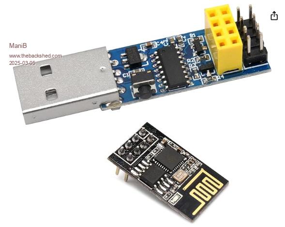 You mean I don't have to flash the module at all? I'll try to test the firmware first sending 'AT' + ENTER with PuTTY |
||||
| Mixtel90 Guru Joined: 05/10/2019 Location: United KingdomPosts: 8911 |
Yep. Normally they respond to AT+ commands. Well, the ones I have do. :) Mick Zilog Inside! nascom.info for Nascom & Gemini Preliminary MMBasic docs & my PCB designs |
||||
| lizby Guru Joined: 17/05/2016 Location: United StatesPosts: 3784 |
The ESP-01 comes with default (but perhaps outdated) AT software, but that will not give you a transparent link. Peter Mather and others have posted several ways to use the AT software, but the process is quite convoluted. If what you want is to be able to remotely access the CMM2 command prompt through the ESP-01, you want ESP-Link. You can find on the forum that several people have done this. The process provided by Grok looks, in general, appropriate. I assume that the pushbutton on the side of your programming module is there to put the ESP-01 into flashing mode--is that what the documentation says? In that case, you are likely to have to hold that button in when you insert the module into the USB socket. Then you can release and it should be in programming mode. PicoMite, Armmite F4, SensorKits, MMBasic Hardware, Games, etc. on FOTS |
||||
| ManiB Senior Member Joined: 12/10/2019 Location: GermanyPosts: 141 |
Hello, I wanted to briefly report my current progress. I am trying to install and set up ESP-LINK on my ESP8266 ESP-01 in order to have a serial to Wi-Fi bridge for my CMM2 G2 V2. The flashing has now worked using the nodemcu-flasher tool: https://github.com/nodemcu/nodemcu-flasher/blob/master/Win64/Release/ESP8266Flasher.exe The esp-link files are available here: http://s3.voneicken.com/esp-link/esp-link-v3.0.14-g963ffbb.tgz After the reset, you can use the smartphone to establish a Wi-Fi connection with the ESP-01. You can then open the page http://192.168.4.1 in the browser to carry out the actual configuration: WiFi station, STA+AP mode, WLAN to which the ESP-01 should connect and the WLAN password. The ESP-01 then connects to the WLAN and is assigned its own IP address (e.g. 10.1.1.194). With the browser, this new IP address can be opened with http://10.1.1.194/home.html to make further settings. In this YouTube video everything is described quite well: https://www.youtube.com/watch?v=mtazgora9xE However, my problem is that the Wi-Fi connection from the WSP-01 to the smartphone is very weak and keeps dropping out. My guess is that my ESP-01 is not working properly, but I don't know for sure. In any case, I can't finalise the configuration. I would now buy another new ESP-01 module, or do anyone have a better idea? |
||||
| ManiB Senior Member Joined: 12/10/2019 Location: GermanyPosts: 141 |
OK, i got it  now I'm able to use COM2 over the air, like: open "COM2:115200" as 4 print #4 "Greetings from CMM2G2V2!" Here's what to do: 1. Get the esp-link files, available here: http://s3.voneicken.com/esp-link/esp-link-v3.0.14-g963ffbb.tgz 2. Get the nodemcu-flasher tool: https://github.com/nodemcu/nodemcu-flasher/blob/master/Win64/Release/ 3. Put the ESP-01 module on the USB programmer and activate the programmer mode 4. Start the nodemcu-flasher tool and make these configuration: 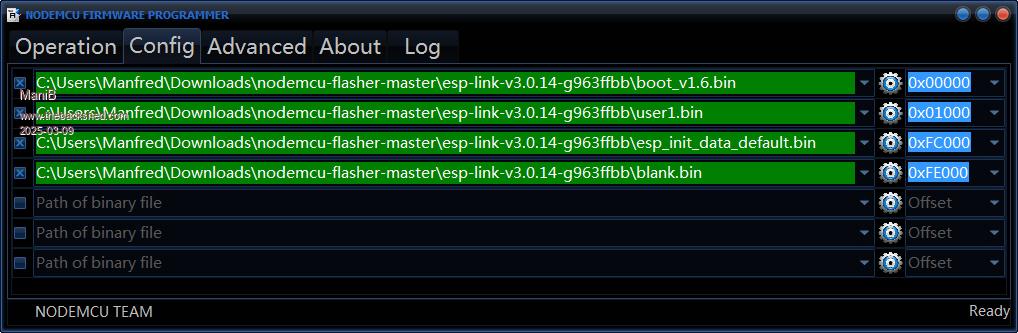 5. Check also the advanced settings 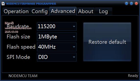 6. Start flashing 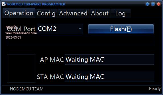 7. After flashing is complete, disconnect the ESP-01 module and put it in your CMM2 G2 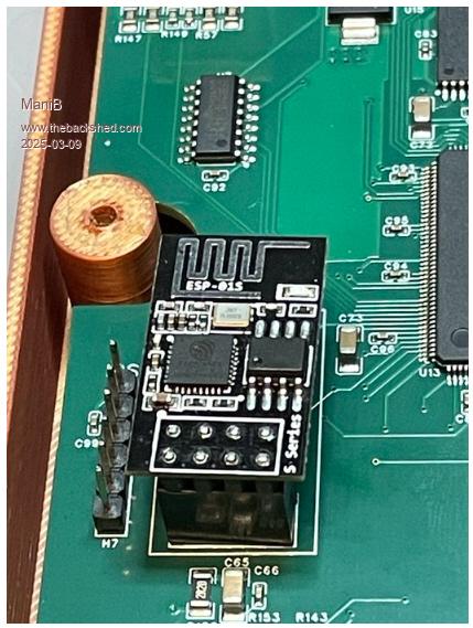 8. Turn on your CMM2 G2, take your smartphone to establish a Wi-Fi connection with the ESP-01. 9. You can then open the web page http://192.168.4.1 in the browser to carry out the actual configuration: WiFi station, STA+AP mode, WLAN to which the ESP-01 should connect and the WLAN password. 10. The ESP-01 then connects to the WLAN and is assigned its own IP address (e.g. 192.168.178.100). With the browser on your PC, this new IP address can be opened with http://192.168.178.100/home.html to make further settings. 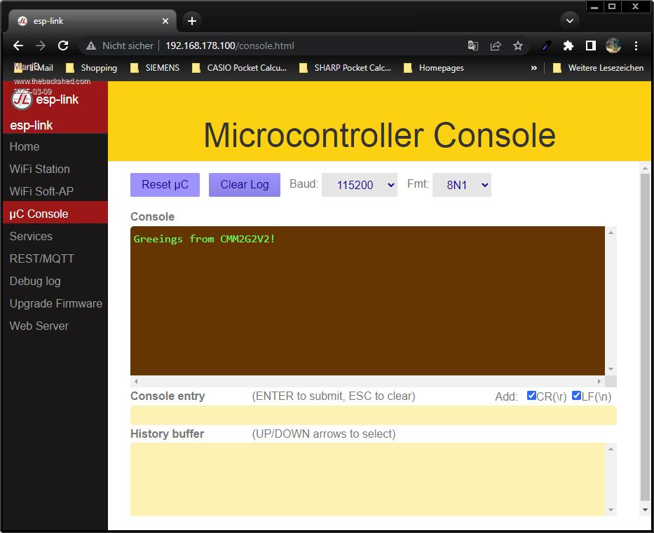 In this YouTube video everything is described quite well: https://www.youtube.com/watch?v=mtazgora9xE Edited 2025-03-09 06:13 by ManiB |
||||
| lizby Guru Joined: 17/05/2016 Location: United StatesPosts: 3784 |
Thanks very much for posting. Glad you got it working. Edited 2025-03-09 06:43 by lizby PicoMite, Armmite F4, SensorKits, MMBasic Hardware, Games, etc. on FOTS |
||||
| The Back Shed's forum code is written, and hosted, in Australia. | © JAQ Software 2026 |
