
|
|
Forum Index : Microcontroller and PC projects : DS3231 RTC Interrupt output
| Author | Message | ||||
| CaptainBoing Guru Joined: 07/09/2016 Location: United KingdomPosts: 2171 |
Morning forum, hope you are all well. I have a question regarding the interrupt on the DS3231 RTC chip. I have need for a reasonably accurate WAKEUP and so I intend to use the Alarm registers in th RTC, and its /INT/ onto the WAKEUP pin(16) of a 170. None of this is particularly amazing but I cannot find in the datasheet for the RTC how the interrupt "fires". I haven't had time to play and I am making the assumption that it goes LO until the flag (in my case A2F) is cleared in the status register? There is plenty of info to get the interrupt working, but not much discussion (and no timing diagram) about the electrical nature of it doing its thing. I have got all this working in software except the /INT/ as I have no access to scope, soldering iron, etc. just now. I put the CPU to sleep for 60 seconds and check that flag when I wake up, it is very reliable and I see A2F go HI indicating the hardware alarm has fired (when minutes=00) so the only thing missing is the hardware wakeup - which leads me to the question regarding how the /INT/ "pulse" looks. anyone any idea? cheers h Edited 2025-04-05 18:25 by CaptainBoing |
||||
| Mixtel90 Guru Joined: 05/10/2019 Location: United KingdomPosts: 8911 |
set two linked inputs to trigger on rising and falling edges respectively. Then a bit of software to identify which triggers first? Mick Zilog Inside! nascom.info for Nascom & Gemini Preliminary MMBasic docs & my PCB designs |
||||
bigmik Guru Joined: 20/06/2011 Location: AustraliaPosts: 2981 |
Hi Capn, Do you have a pull-up resistor, guess at 10k, on the INT pin? The INT pin is open drain and will drop (pulse??) LOW when the alarm registers match the time you set. You are correct that there is bugger all in the manner of timing diagrams etc, no pulse duration etc. I would think that with a pull-up resistor to 5v or 3v3 you should be able to directly connect the INT pin to the WAKE-UP pin Regards Mick . Mick's uMite Stuff can be found >>> HERE (Kindly hosted by Dontronics) <<< |
||||
| phil99 Guru Joined: 11/02/2018 Location: AustraliaPosts: 3293 |
Re the duration of the alarm interrupt. The data says the INT/SQW pin goes low while the clock registers match either set of alarm registers. The LSB of the clock registers is Seconds so I assume the "match" lasts one second, so the low pulse would be 1S. Edited 2025-04-05 21:11 by phil99 |
||||
| twofingers Guru Joined: 02/06/2014 Location: GermanyPosts: 1761 |
It's not directly related to the question, but I remembered that a few months ago I created (or played around with) some alarm routines for DS3231. Maybe they'll be useful to someone. I'm not sure if I found the right file, but I think the program illustrates the RTC and the alarm status well. Alarm (2) is set with the "A" key. A routine for Alarm 1 is also available. 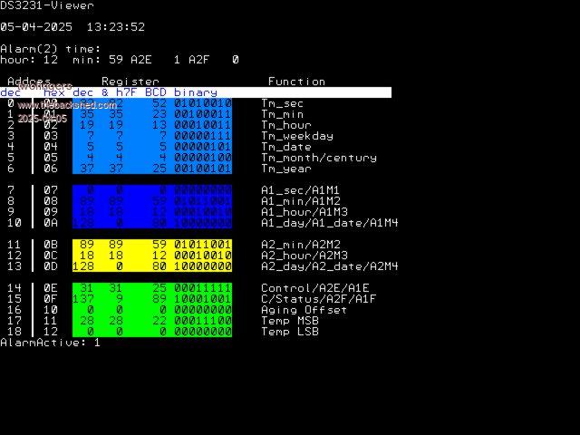 DS3231view.zip Regards MIchael causality ≠ correlation ≠ coincidence |
||||
| ville56 Guru Joined: 08/06/2022 Location: AustriaPosts: 531 |
Please try page 12 of the document appended, maybe that helps a bit. DS3231.pdf Gerald 73 de OE1HGA, Gerald |
||||
| CaptainBoing Guru Joined: 07/09/2016 Location: United KingdomPosts: 2171 |
Thanks everyone for your input. @Mixtel: Good idea but I am now home and have access to the power of the shed  Thanks anyway Thanks anyway@BigMik: Thanks for this Mick, I do have a pull up on the pin and I put a 10nF to ground as well just to snub any noise. @TwoFingers: I like that prog. It would have saved me all the horrible bits n bobs testing to get this far. @ville56: Thanks that doc seems to be a re-brand of the same one I have. Sadly, it also misses the bit where it tells you how long the /INT/ pulse will be (see below) @Phil99 that was my thinking t0o - that it was just a logic function on the registers. Now I managed to scope things and I put a "press any key" right before I reset the flag, I can confirm that the /INT/ pin remains LO while the flag persists - A2F in my case but I am gonna make the jump and say its probably the same for A1F too. And below you can see my trace output: First figure is the time from going into SLEEP to the time taken to come out and do some checks... 400 odd mS from the gentle 5MHz '170  but something important is revealed... but something important is revealed...60431 15:54:54 - 60430 15:55:54 - 60431 15:56:54 - 60431 15:57:54 - 60430 15:58:55 - 60431 15:59:55 - 16:00:55 Alarm triggered 60422 16:01:55 - 60431 16:02:56 - 60432 16:03:56 - 60430 16:04:56 - 60431 16:05:56 - 60431 16:06:57 - ... did you see? the /INT/ going LO did not trigger the WAKEUP pin(16) - otherwise how did we get to 55 seconds in and we didn't miss a beat between the timings either side?  So now, I suspect WAKEUP is not working... I have toned out the back-wiring I did and it is all there so it must be software... The MicroMite doc says of CPU SLEEP: CPU Sleep The CPU SLEEP command will put the processor to sleep for a certain number of seconds or monitor the WAKEUP pin for a wakeup signal. During sleep the current drain is less than 40 μA. Normal use for the command is CPU SLEEP seconds and in that case the CPU will sleep for the specified number of seconds. Alternatively the sleep can be aborted early by a change in state of an I/O pin. Eg: CPU SLEEP seconds, abortpin. If the timeout is not specified this command will automatically configure the WAKEUP pin as a digital input. During sleep this pin will be monitored and the CPU woken up when its input changes state (ie, goes from high Micromite User Manual Page 15 to low or low to high). The wakeup signal could be a button press, an incoming signal or some other external interrupt. This form of wakeup us very fast (< 1ms)... in my code I have CPU Sleep 60 expecting the WAKEUP pin toggle to rouse the cpu ... BUT ... re-interpretting that section from the manual, I think it means that if you specify a time and no abortpin, WAKEUP doesn't work automatically. I want to sleep 60 seconds OR bet INTerrupted So now I have configured pin 16 as DIN and I have CPU Sleep 60,16 it approaching the hour........ |
||||
| CaptainBoing Guru Joined: 07/09/2016 Location: United KingdomPosts: 2171 |
... and bingo. So I think the wording for sleep can be interpretted on thhe sly if you are a dolt like me. SLEEP sleeps and only automatucally wakes (level change on pin 16) if you don't set a time If you set a time, you must also set the abortpin (which I did to 16) if you want it - it won't automatically use WAKEUP So now my code achieves the "sleep for n seconds but wake if necessary" and my DS3231 PDF print-out has some extra scribble on it Thanks everyone. h Edited 2025-04-06 04:25 by CaptainBoing |
||||
TassyJim Guru Joined: 07/08/2011 Location: AustraliaPosts: 6538 |
A bit late to the party but this is another example of setting and controlling the alarms. CMM2 so references to I2C3 will need changing. ' CMM2 RTC alarm clock - TassyJim OPTION AUTORUN ON DIM RTCbuff(20) DIM RTCaddr = &h68 DIM RTCtime$, RTCdate$ CLS PRINT "MM Time = ";TIME$;" ";DATE$;" ";dow$(doweek(DATE$)) DO PRINT "1 Set RTC" PRINT "2 Read RTC" PRINT "3 Set MM from RTC" PRINT "4 Input alarm times" PRINT "5 Arm alarms" PRINT "6 Clear alarm" PRINT "Choice?" DO c$ = INKEY$ LOOP UNTIL c$ <>"" IF c$ = "1" THEN setRTC IF c$ = "2" THEN showAll IF c$ = "3" THEN showAll : setMM IF c$ = "4" THEN doSetAlarm IF c$ = "5" THEN doArmAlarm IF c$ = "6" THEN clearAlarm LOOP SUB showAll readRTC getRTC PRINT "RTC Time = ";RTCtime$;" ";RTCdate$;" ";dow$(doweek(RTCdate$)) PRINT "MM Time = ";TIME$;" ";DATE$;" ";dow$(doweek(DATE$)) AL1$ = getAlarm$(1) AL2$ = getAlarm$(2) PRINT "Alarm 1 ";AL1$ PRINT "Alarm 2 ";AL2$ control$ = BIN$(RTCbuff(14),8) PRINT "Control ";control$ status$ = BIN$(RTCbuff(15),8) PRINT "Status ";status$ END SUB SUB setRTC ' set RTC to MM time LOCAL INTEGER BCDh, BCDm, BCDs, BCDd, BCDmo, BCDy, BCDw LOCAL now$, today$ now$=TIME$ today$=DATE$ BCDh = VAL("&H"+LEFT$(now$, 2)) BCDm = VAL("&H"+MID$(now$, 4, 2)) BCDs = VAL("&H"+MID$(now$, 7,2)) BCDd = VAL("&H"+LEFT$(today$, 2)) BCDmo = VAL("&H"+MID$(today$, 4, 2)) BCDy = VAL("&H"+RIGHT$(today$, 2)) BCDw = doweek(today$) ' Write Time to RTC I2C3 OPEN 100,100' Enable I2C I2C3 WRITE RTCaddr, 0, 8,0, BCDs, BCDm, BCDh, BCDw, BCDd, BCDmo, BCDy I2C3 CLOSE PRINT "0=ok 1=nack 2=timeout "; MM.I2C PRINT "RTC set to: ";now$;" ";today$ END SUB SUB readRTC I2C3 OPEN 100, 200 ' Enable I2C I2C3 WRITE RTCaddr, 0, 1, 0 I2C3 READ RTCaddr, 0, 19, RTCbuff(0) I2C3 CLOSE END SUB SUB getRTC LOCAL RTCsec$,RTCmin$,RTChr$,RTCwday$,RTCday$,RTCmon$,RTCyr$ RTCsec$ =HEX$((RTCbuff(0) AND &H7F),2) RTCmin$ =HEX$((RTCbuff(1) AND &H7F),2) RTChr$ =HEX$((RTCbuff(2) AND &H3F),2) RTCwday$=HEX$((RTCbuff(3) AND &H07),2) RTCday$ =HEX$((RTCbuff(4) AND &H3F),2) RTCmon$ =HEX$((RTCbuff(5) AND &H1F),2) RTCyr$ ="20"+HEX$((RTCbuff(6)),2) RTCtime$=RTChr$+":"+RTCmin$+":"+RTCsec$ RTCdate$=RTCday$+"-"+RTCmon$+"-"+RTCyr$ END SUB SUB setMM TIME$=RTCtime$ DATE$=RTCdate$ PRINT "MM Time set!" END SUB FUNCTION getAlarm$( n) LOCAL ALsec$,ALmin$,ALhr$,ALwd$ IF n = 1 THEN ALsec$ =HEX$((RTCbuff(7) AND &H7F),2) ALmin$ =HEX$((RTCbuff(8) AND &H7F),2) ALhr$ =HEX$((RTCbuff(9) AND &H3F),2) ALwd$ =HEX$((RTCbuff(10) AND &H3F),2) ALmode$=STR$(bit(RTCbuff(10),6))+STR$(bit(RTCbuff(7),7))+STR$(bit(RTCbuff(8),7))+STR$(bit(RTCbuff(9),7)) ALMode$ = ALmode$+STR$(bit(RTCbuff(14),0))+STR$(bit(RTCbuff(15),0)) ELSE ALsec$ = "00" ALmin$ =HEX$((RTCbuff(11) AND &H7F),2) ALhr$ =HEX$((RTCbuff(12) AND &H3F),2) ALwd$ =HEX$((RTCbuff(13) AND &H3F),2) ALmode$=STR$(bit(RTCbuff(13),6))+STR$(bit(RTCbuff(11),7))+STR$(bit(RTCbuff(12),7))+"0" ALMode$ = ALmode$+STR$(bit(RTCbuff(14),1))+STR$(bit(RTCbuff(15),1)) ENDIF getAlarm$=ALhr$+":"+ALmin$+":"+ALsec$+"-"+ALwday$+"-"+ALmode$ END FUNCTION SUB doSetAlarm LOCAL at1$, at2$ INPUT "Alarm Time 1 ",at1$ INPUT "Alarm Time 2 ",at2$ IF at1$ <>"" THEN setAlarm(at1$,1) IF at2$ <>"" THEN setAlarm(at2$,2) END SUB SUB setAlarm(atime$, n) LOCAL INTEGER BCDh, BCDm, BCDs, BCDd BCDh = VAL("&H"+LEFT$(atime$, 2)) BCDm = VAL("&H"+MID$(atime$, 4, 2)) BCDs = VAL("&H"+MID$(atime$, 7,2)) BCDd = VAL("&H"+MID$(atime$, 10,2)) OR &b10000000 ' hours and minutes match I2C3 OPEN 100,100' Enable I2C IF n = 1 THEN I2C3 WRITE RTCaddr, 0, 5,7, BCDs, BCDm, BCDh, BCDd ELSE I2C3 WRITE RTCaddr, 0, 4,11, BCDm, BCDh, BCDd ENDIF I2C3 CLOSE END SUB SUB doArmAlarm LOCAL al INPUT "alarm to arm ", al armAlarm(al) END SUB SUB armAlarm n LOCAL alCMD readRTC ' SELECT CASE n CASE -1 ' disarm alarm 1 alCMD = RTCbuff(14) AND &b11111110 CASE 1 ' arm alarm 1 alCMD = RTCbuff(14) OR &b00000001 CASE -2 ' disarm alarm 2 alCMD = RTCbuff(14) AND &b11111101 CASE 2 'arm alarm 2 alCMD = RTCbuff(14) OR &b00000010 END SELECT I2C3 OPEN 100,100 I2C3 WRITE RTCaddr, 0, 2,14,alCMD i2c3 CLOSE END SUB ' SUB clearAlarm alCMD = RTCbuff(15) AND &b11111100 I2C3 OPEN 100,100 I2C3 WRITE RTCaddr, 0, 2,15,alCMD i2c3 CLOSE PRINT "alarm state cleared ";BIN$(alCMD,8) END SUB FUNCTION doweek(theDate$) AS INTEGER LOCAL INTEGER dy, month, year, dayofyear, dayz dy = VAL(LEFT$(theDate$, 2)) month = VAL(MID$(theDate$, 4, 2)) year = VAL(RIGHT$(theDate$, 4)) dayofyear= dy+INT((month-1)*30.57+0.5) IF month >2 THEN dayofyear= dayofyear-1 IF (year/4)>0 THEN dayofyear= dayofyear-1 ENDIF dayz= INT((year-1900)*365.25)+dayofyear+1 doweek= dayz-1-INT((dayz-1)/7)*7 END FUNCTION FUNCTION dow$(d) dow$=MID$("SUNMONTUEWEDTHUFRISATSUN",d*3+1,3) END FUNCTION FUNCTION checkRTC() LOCAL rcvbuf 'i2caddr = &h51 ' PCF8563 I2C address 'i2caddr = &h68 ' DS1307, DS3231, DS3232 I2C3 OPEN 100, 200 PAUSE 20 I2C3 READ RTCaddr, 0,1, rcvbuf PRINT "checking DSxxxx";MM.I2C I2C3 CLOSE checkRTC = MM.I2C END FUNCTION FUNCTION bit(n AS INTEGER,b AS INTEGER) AS INTEGER ' return value of bit b (0 - 63) of n bit = (n >> b) AND 1 END FUNCTION FUNCTION setBit(n AS INTEGER,b AS INTEGER) AS INTEGER setBit = n OR (1 << b) END FUNCTION FUNCTION clearBit(n AS INTEGER,b AS INTEGER) AS INTEGER clearBit = n AND INV(1 << b) END FUNCTION I used it to wake the CMM2 up each morning. Jim VK7JH MMedit |
||||
| PhenixRising Guru Joined: 07/11/2023 Location: United KingdomPosts: 1961 |
Just attempted to run this on the PicoMite. All I have changed is I2C3 to I2C2 but getting this error. Any ideas (looks fine to me)  |
||||
| dddns Guru Joined: 20/09/2024 Location: GermanyPosts: 843 |
Bit a token? |
||||
| PhenixRising Guru Joined: 07/11/2023 Location: United KingdomPosts: 1961 |
Doesn't appear to be but I'm thinking that MMBasic may not like it...Should've tried changing that before I reported  |
||||
| PhenixRising Guru Joined: 07/11/2023 Location: United KingdomPosts: 1961 |
Yeah, PicoMite doesn't like a function named "bit". I changed it to Italian "beet" |
||||
| The Back Shed's forum code is written, and hosted, in Australia. | © JAQ Software 2026 |
