
|
|
Forum Index : Microcontroller and PC projects : Waveshare 7 & 10" DVI displays
| Page 1 of 3 |
|||||
| Author | Message | ||||
| IanT Senior Member Joined: 29/11/2016 Location: United KingdomPosts: 130 |
I've been thinking about how best to produce two simple Boot-to-Basic PicoMite systems as gifts for my two eldest grandchildren. A usable screen, with combined CPU unit, with full-sized external USB keyboard would seem to be a good solution, given their likely use. They don't need to be "portable" as such, just reasonably self-contained. I've noticed these 7"/10" DVI displays on the Waveshare site that provide a Pico socket on the back. They seem reasonably priced (£25'ish) and would save me a lot of work hacking a custom system. I can produce simple cases for them, together with plug-in mains power. https://www.waveshare.com/pico-dvi.htm?sku=25510 However, these displays use a pin-out that is different to the standard Picomite HDMI set-up. So my (quite probably dumb) question is - Is it possible to re-define the pins used for the HDMI signals? If so, will that then work with this "DVI" screen? Regards, IanT |
||||
| matherp Guru Joined: 11/12/2012 Location: United KingdomPosts: 11517 |
No: the HSTX pins are hard wired in the RP2350 and can't be changed. |
||||
| Mixtel90 Guru Joined: 05/10/2019 Location: United KingdomPosts: 8911 |
In theory one could make a hardware adapter to accept a Pico 2 and with a 40-pin plug on it to plug into the Waveshare socket. That would be an interesting exercise. A bit pointless as you can't have 1024x600 resolution though. . Edited 2025-05-01 22:05 by Mixtel90 Mick Zilog Inside! nascom.info for Nascom & Gemini Preliminary MMBasic docs & my PCB designs |
||||
| mozzie Guru Joined: 15/06/2020 Location: AustraliaPosts: 385 |
G'day IanT With a simple breadboard adapter these DVI screens work very well, the native 1024 x 600 resolution is a pain but they scale to whatever you drive them with. Can confirm 640x480,800x600,1024x768 and 1280x720 all work fine, haven't tried the others yet. 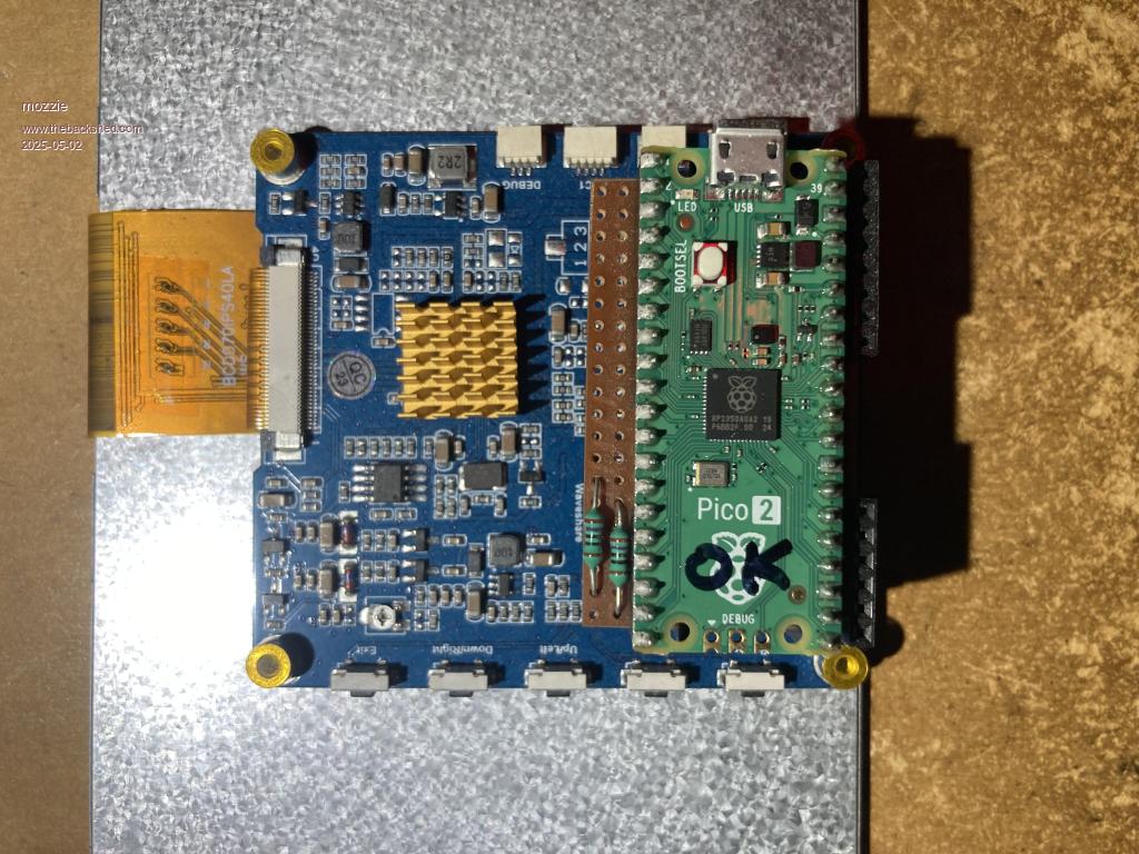 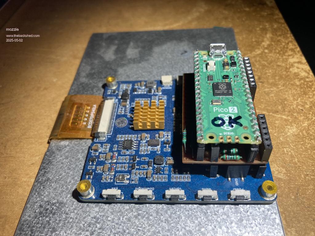 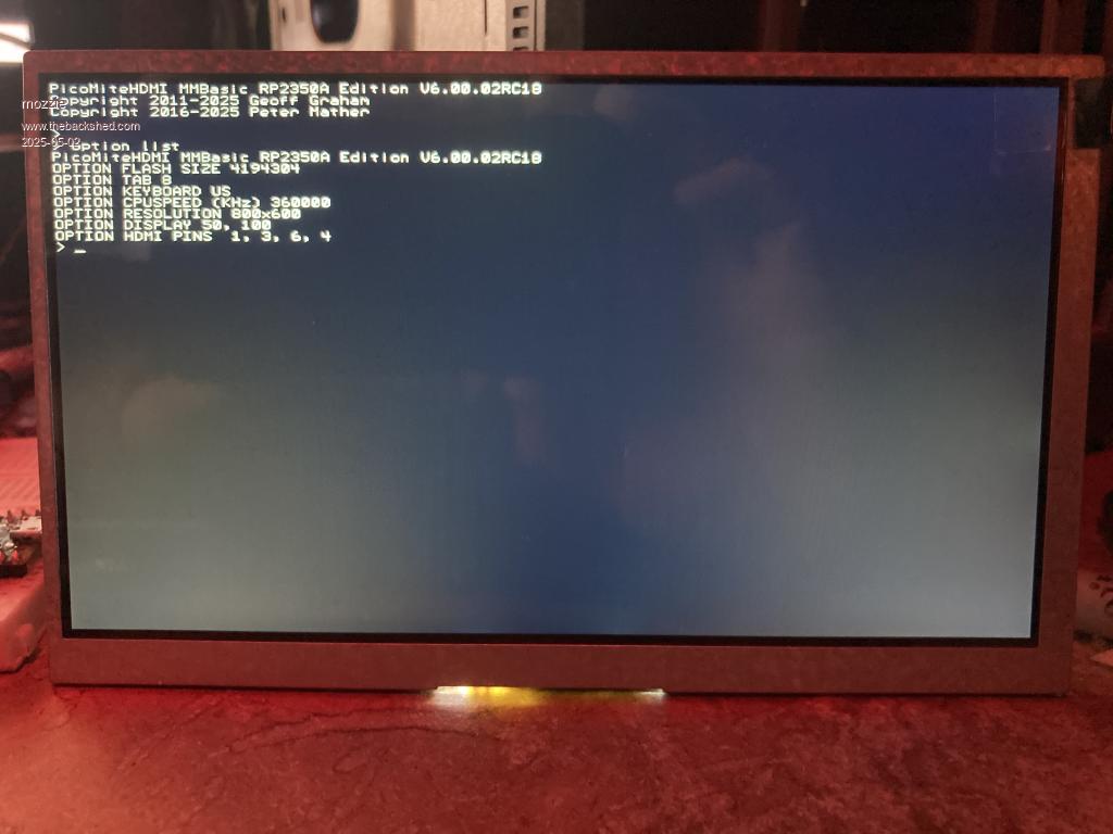 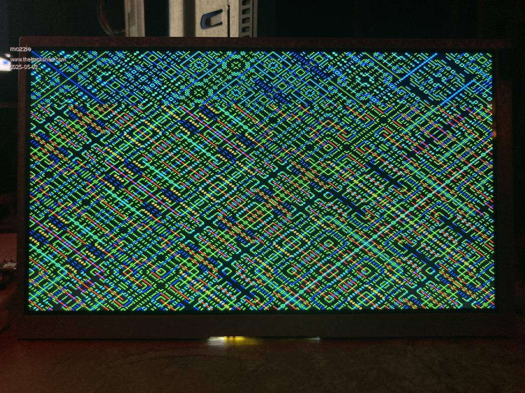 Photos don't do the real thing justice, this is the 7" version. Regards, Lyle. |
||||
| lizby Guru Joined: 17/05/2016 Location: United StatesPosts: 3784 |
Very nice. I assume a JLCPCB board could do the configuring. Do you have a schematic? PicoMite, Armmite F4, SensorKits, MMBasic Hardware, Games, etc. on FOTS |
||||
| IanT Senior Member Joined: 29/11/2016 Location: United KingdomPosts: 130 |
Thank you for the replies everyone. Your solution looks like a really good fit for my need Mozzie. I can manage a bit of veroboard bodgery if necessary but will admit a JLCPCB board would be a much neater way to do it! For the small difference in price, I think I'll use the 10" display. Regards, IanT |
||||
| mozzie Guru Joined: 15/06/2020 Location: AustraliaPosts: 385 |
G'day, See below for... well... ummm... a diagram...  You loose GP8,9,10,11 on the PICO side and GP16,17,18,19 on the DVI side using veroboard. These could be connected with jumpers of course with a bit of juggling. Use option HDMI PINS 1,3,6,4 if you do it this way. Also tested 720x400 and 848x480 resolution and can confirm they work as widescreen modes. 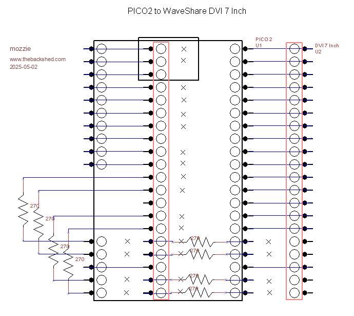 Regards, Lyle. |
||||
| IanT Senior Member Joined: 29/11/2016 Location: United KingdomPosts: 130 |
Thank you for that Lyle. It took me a few seconds to understand what I was looking at but I get the general idea. I have a 'Babysit' day today but I will print this out and look at it in more detail this evening. That's assuming I have any life/energy left in me by then. This child is nearly 3yrs old (and not quite yet up to learning Basic) but he can still run us ragged :-) Looking at the debate about a 'PicoCalc' alternative on another thread, I can see the attraction of a Psion (remember them?) type hand held computer/organiser. However, I think a standalone MMB unit, with usable keyboard and larger screen would be preferable for many people... ..and of course I also have an Android phone in my pocket these days. BTW - If some kind person can do a PCB design based on Mozzie's scheme (ideally with an SD card reader onboard), I'll get a few made by JCLPCB as a further proof of concept... Regards, IanT |
||||
| Mixtel90 Guru Joined: 05/10/2019 Location: United KingdomPosts: 8911 |
I'm just having a play with a design. I'm wondering if I can fit an audio module on too.... Fairly early days. Mick Zilog Inside! nascom.info for Nascom & Gemini Preliminary MMBasic docs & my PCB designs |
||||
| matherp Guru Joined: 11/12/2012 Location: United KingdomPosts: 11517 |
https://www.thebackshed.com/forum/ViewTopic.php?TID=17645&PID=233645#233645 https://www.thebackshed.com/forum/ViewTopic.php?TID=17615&PID=232839#232839 |
||||
| Mixtel90 Guru Joined: 05/10/2019 Location: United KingdomPosts: 8911 |
So far... 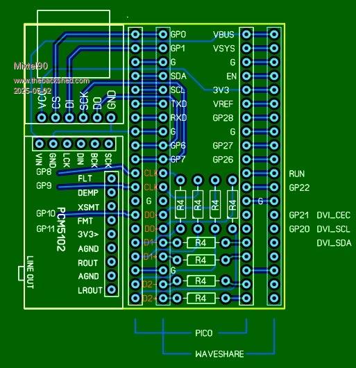 Mick Zilog Inside! nascom.info for Nascom & Gemini Preliminary MMBasic docs & my PCB designs |
||||
| gadgetjack Senior Member Joined: 15/07/2016 Location: United StatesPosts: 233 |
I like that design. May try this avenue myself. |
||||
| Mixtel90 Guru Joined: 05/10/2019 Location: United KingdomPosts: 8911 |
I'm not far off now. I've added some GPIO pins and a reset button. Mostly tidying up now. Mick Zilog Inside! nascom.info for Nascom & Gemini Preliminary MMBasic docs & my PCB designs |
||||
| mozzie Guru Joined: 15/06/2020 Location: AustraliaPosts: 385 |
G'day, A couple more observations The 7" display drags: 0.5A with backlight at MIN 0.9A with backlight at MID 1.5A with backlight at MAX So might be a good idea to power via the USB-C on board. The 5V VBUS is not powered so USB firmware will be a problem. The Waveshare schematic is not much help. The controller on the board is a RTD2281 IanT, Hope you survived the baby sitting adventure... Similar idea to yours, fit a PS2 keyboard and SD card for an all in one MMBasic unit. There is a design in the "to do" list however I cut boards from CAD with an engraving machine (2hr turnaround  ) so hopefully Micks will work for you. ) so hopefully Micks will work for you.Mick, That looks pretty good so far, any chance of a PS2 socket? Regards, Lyle. |
||||
| Mixtel90 Guru Joined: 05/10/2019 Location: United KingdomPosts: 8911 |
PS2 not on board at the moment. You could connect one to the GPIO pins though. I'm not sure I'd want to hang a keyboard cable off the piggyback board. I've just suspended a mini RTC over the top of the uSD card socket. :) I'm picking up 5V from the Waveshare VBUS connection and feeding it into VSYS via a Schottky diode on the Pico. The Waveshare can power the Pico but not vice versa. The Pico can then be programmed using it's own USB connection, which may not be able to supply the current as it's not USB-C. The circuit shows the USB-C VBUS going directly to the Pico VBUS. Not a good arrangement. Mick Zilog Inside! nascom.info for Nascom & Gemini Preliminary MMBasic docs & my PCB designs |
||||
| mozzie Guru Joined: 15/06/2020 Location: AustraliaPosts: 385 |
G'day Mick, Thats interesting, if you have a diagram indicating the USB-C on the main board is connected to VBUS then there must be at least 2 versions of the main board. There is no version info on the board here. The schematic I have here shows no connection to VBUS and this is confirmed on the board itself, VBUS is not connected, VSYS is connected to the 5V from USB-C on main board directly. Adding a jumper to your design (VBUS-VSYS) may solve the problem and allow USB firmware to power keyboards etc. Good idea fitting a RTC Regards, Lyle. |
||||
| Mixtel90 Guru Joined: 05/10/2019 Location: United KingdomPosts: 8911 |
You're right - I'd misread the info. It's got 5V on pin 39, intended for VSYS. That's fine. I'll feed it to VBUS via a diode. To install or update MMBasic unplug the display and connect the PC to the Pico USB as usual. You can then use the Pico's USB in host mode for a hub while you power the system from the display's USB. The diode will prevent a big current draw from the PC. According to the circuit diagram we don't need to provide DVI resistors or I2C pullups. They are already there. I think I'll move the UART connector to GP8/GP9. It's of more use to us. It's still COM2 anyway, which is equally inconvenient. :) There aren't many COM1 pins but I'll try to do something with GP0/GP1. Mick Zilog Inside! nascom.info for Nascom & Gemini Preliminary MMBasic docs & my PCB designs |
||||
| IanT Senior Member Joined: 29/11/2016 Location: United KingdomPosts: 130 |
I'm very pleased you guys know what you are talking about! Mozzie - I have a small 3020 CNC router but haven't really cut anything (but air) just yet. When I got my 3D printer it was more from curiosity than need but I have found it very useful for small parts (enclosures, pipe adaptors, custom clips, jig and even the odd toy..). For my design work, I started with Open SCAD but quickly moved to Solid Edge. Learning 3D CAD has been quite a challenge but 5yrs later I'm pretty good at the basics. Once you have the STL then 3D printing it is fairly straightforward. However, CNC is (in my opinion) another whole level of difficulty up from 3DP. I'm having to learn CAM, some G-Code, how to use a G-Code Sender and of course the whole speed & feed thing. It's taking me a lot longer to get going with CNC than 3DP but I do hope to try some simple PCBs before too long. I'd be curious what CAM & PCB layout software you use? Mick - I look forward to seeing your final solution and apologise that I'm not able to contribute very much to this conversation. I have great fun with my Mites but will admit I do struggle to stay up with the rate of change/improvement. It is amazing/wonderful but also just a little overwhelming sometimes. It would be great to be able to do everything (and very tempting to try to do so) but in reality, I have finite time and energy and too many things on my to-do list, without adding anything more. So thank you both for your help & expertise, it's much appreciated. Regards, IanT |
||||
| Mixtel90 Guru Joined: 05/10/2019 Location: United KingdomPosts: 8911 |
That's why I leave the software to others. My programming is pretty bad... :) Mick Zilog Inside! nascom.info for Nascom & Gemini Preliminary MMBasic docs & my PCB designs |
||||
| mozzie Guru Joined: 15/06/2020 Location: AustraliaPosts: 385 |
G'day, Mick, the circuit diagram is not to be believed....  The DVI resistors on the main board are 0R links, I get 60ma to gnd with DMM, current limit resistors might be a good idea IanT, Oh how true, and surely this applies to many members here on the backshed.  I am very lucky to have a ROLAND CAMM-Scribe CS-20 engraving machine, purchased in approx 1997. This is perfect for making front panels etc with its inbuilt electric spindle drive. We found that a micro die grinder fits with a small machined adaptor and accepts 1/8 carbide PCB mills and drills, PCB production was now a goer Software wise, for intricate PCB's I still use CircuitMaker / TraxMaker to draw the design and IsoPro to create the cut paths and drill files. This is all WIN98 era software. Most of my PCB's are for power electronics / auto electrics so using CAD to draw all the holes, then lines where I dont want copper, and plot direct to the CAMM-Scribe machine, see pic below Have been tinkered with 3D filament and resin printers as well and they are both awesome in there own way. Also aquired a 6040 CNC machine a while ago after the previous owner found it "all too hard", but having repaired several CNC machines agree there is a lot to learn and expensive mistakes to make. Since I am unemployed for the first time in 40 years and enjoying some long service leave, I think its time to see if I can figure it out. Time also to peruse the CNC forum here on TheBackShed. Another learning curve to straighten..... 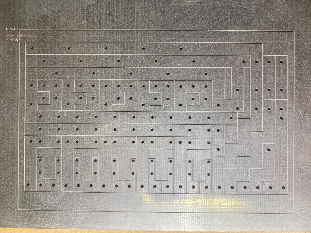 Relay PCB for something long ago 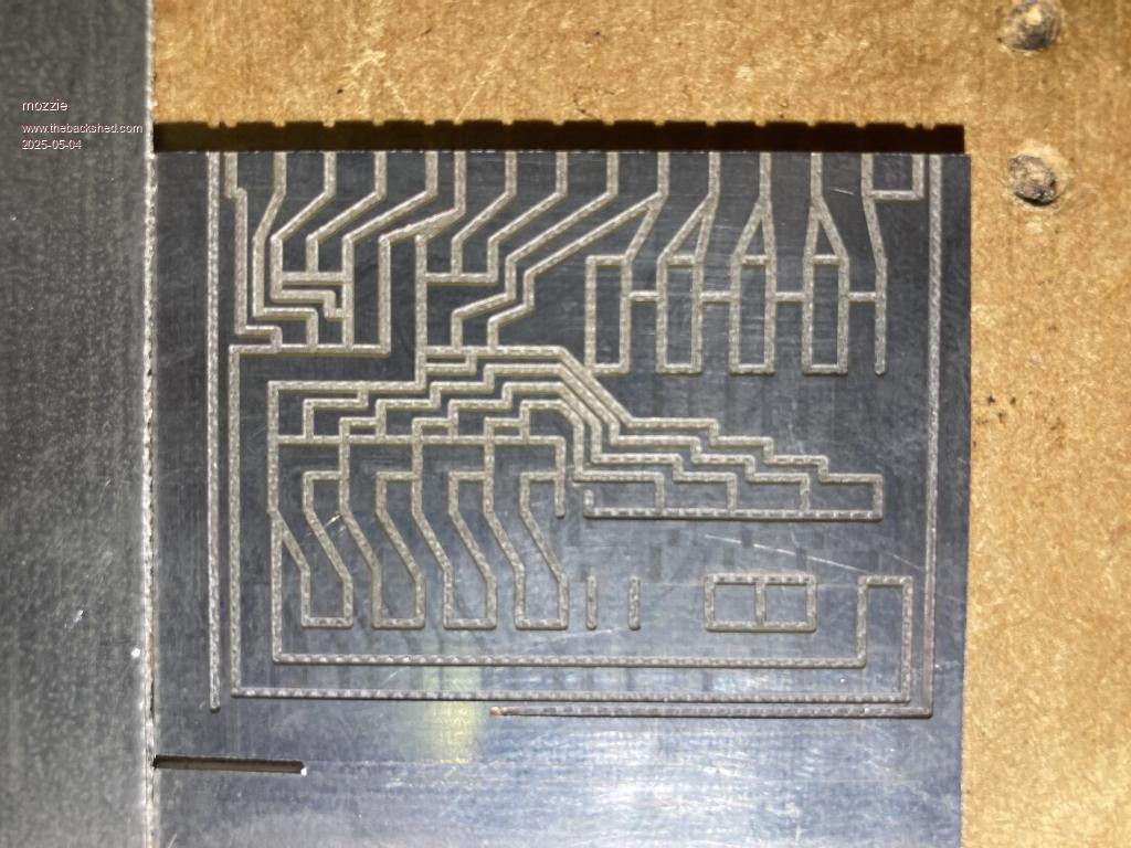 Oooops, cutter too wide 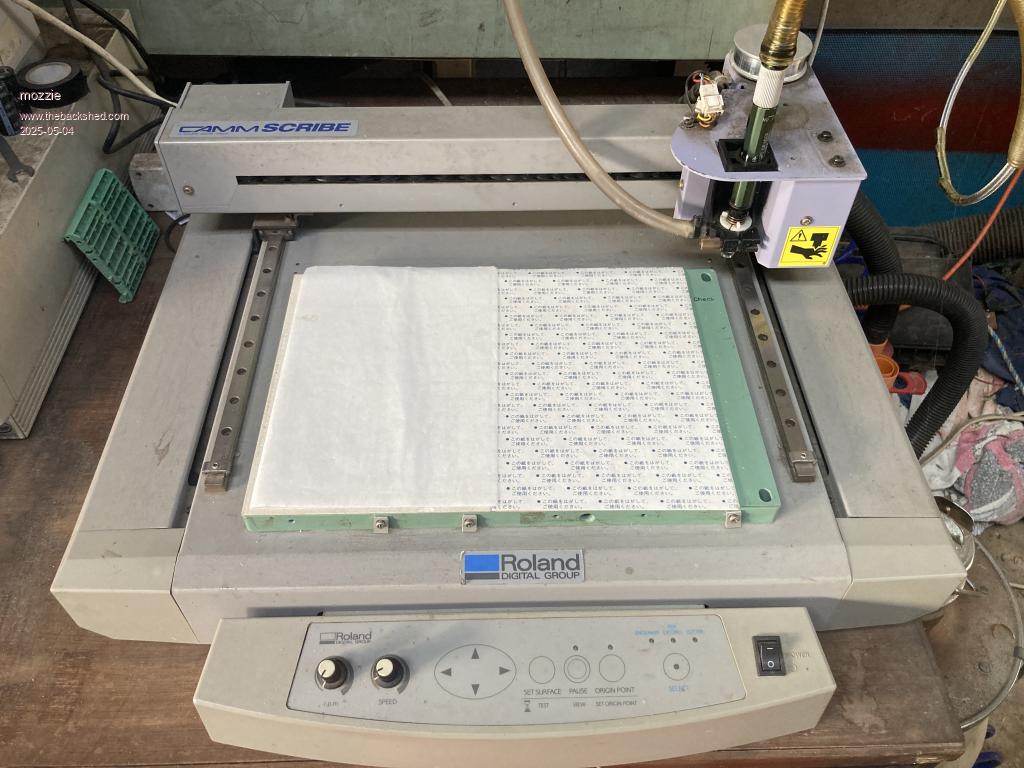 28 years old and still going strong 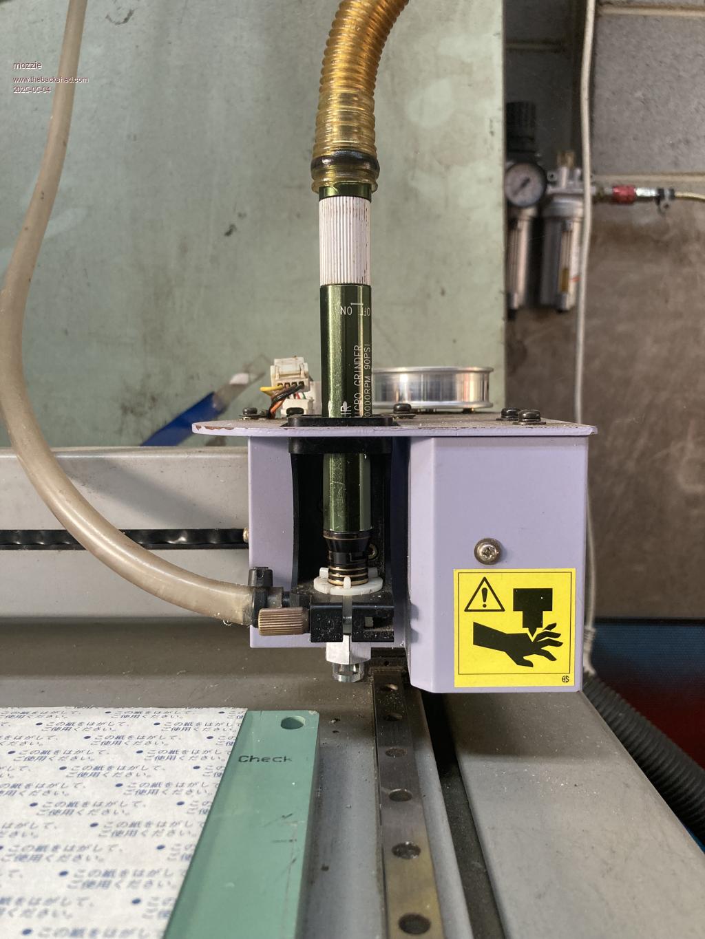 Micro Die Grinder with adaptor Regards, Lyle. |
||||
| Page 1 of 3 |
|||||
| The Back Shed's forum code is written, and hosted, in Australia. | © JAQ Software 2026 |
