
|
|
Forum Index : Microcontroller and PC projects : Hello and My PicoMite Build!
| Page 1 of 3 |
|||||
| Author | Message | ||||
| g0730n Newbie Joined: 14/05/2025 Location: United StatesPosts: 18 |
I ended up building my PicoMite on a protoboard and used components I already had. It all works great and all that is left to do is print a 3d case for it. The AC adapter for the laptop i use for all my printing failed recently so I am waiting for the new one in mail. Features: -VGA OUTPUT -USB KEYBOARD -DS3231 RTC -DHT11 Temp/Humidity Sensor -SD Card -2 LEDS (GREEN = PLUGGED IN, POWER OFF), (RED = PLUGGED IN, POWER ON) -Breakout pin header for unused GPIO (Currently not wired up) -2 Passive Piezo Buzzers for audio output. I did not know if this would actually work for playing a WAV, but it does! -Slide switch for Power -RESET Button -TP4056 LiPo Battery charger (I didn't have Micro USB breakout, so ended up using one of these for the breakout. I may implement a battery in future for something so there it is) 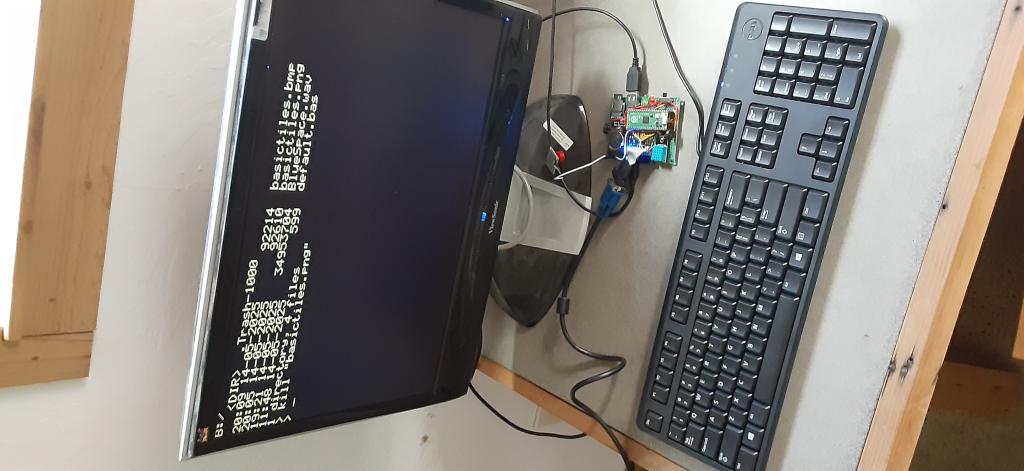 I used Pogo Pins for the USB D+ and D- to avoid soldering directly to pico test points, it actually seemed to work great! 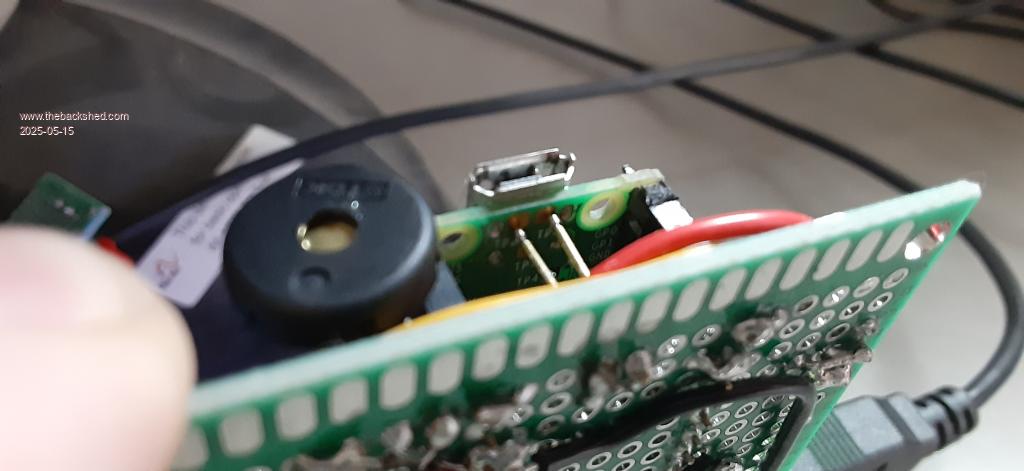 My protoboard soldering work is never pretty, and takes about 10x longer than a PCB, but here are some more pics. 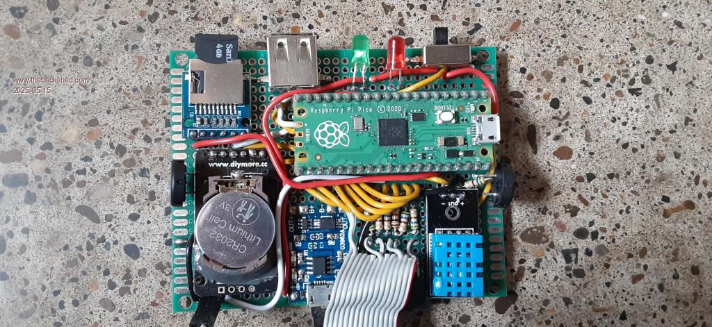 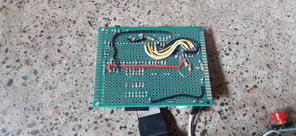 One thing I am wondering is if I can have any other serial devices attached if I also have SD Card installed on RP2040 VGA USB. I would like to interface with an nrf24l01 possibly in the future. But aside from that I am going to play around with writing some BASIC programs! The graphics capabilities of PicoMite are looking pretty awesome makes me want to make a small game. |
||||
| dddns Guru Joined: 20/09/2024 Location: GermanyPosts: 843 |
Well done! sdcard and serial are completely different and yes, you can have a second serial port for your basic program to access. This is very good described in the manual appendix A and following. Happy tinkering and try a 2350 for even more fun Edited 2025-05-15 07:44 by dddns |
||||
| stanleyella Guru Joined: 25/06/2022 Location: United KingdomPosts: 2807 |
nice one |
||||
| phil99 Guru Joined: 11/02/2018 Location: AustraliaPosts: 3293 |
Welcome to the forum, making your own layout on protoboard or stripboard allows easy modification for new ideas. Adding the nrf24l01 might require using the second SPI channel (SPI2) as I don't think the VGA versions support System SPI, which may have allowed sharing the SPI bus with the SD card. Appendix D in the manual describes SPI. Edit. That a Chip Enable pin is used makes me wonder, despite that, if it is possible to use the same SPI as the SD card. Someone who has tried it may let us know. Edited 2025-05-15 09:35 by phil99 |
||||
| g0730n Newbie Joined: 14/05/2025 Location: United StatesPosts: 18 |
I usually make the first version of anything on breadboard > protoboard > then PCB. Usually the protoboard version because I want to make the first one without waiting for PCB, but yeah it does really help with adding/removing stuff. That bit about the SD card on VGA version only available to SD card in manual was what got me confused. I think I was thinking that meant no other SPI was available, but it makes sense that the second bus is available. The only version of BASIC I had used at this point is Arduino BASIC, where line numbers are needed in programs. I had a lot of fun with that. MMBasic is way more advanced and the little bit I have done on it so far is quite enjoyable! |
||||
| Volhout Guru Joined: 05/03/2018 Location: NetherlandsPosts: 5931 |
The PICO has 2 SPI hardware blocks. In the microcontroller version, you can assign SYSTEM SPI to one of these, and share the SPI bus between LCD , Touch, and SD card. Quite clever. The hardware SPI blocks however have designated pins. In the VGA/HDMI version, there is no touch, no lcd, so the SPI is used only for SD card. To be flexible in what pins to use, the SD card (SPI) interface is "bit-banged". So every pin can be used for every SD card signal. So it is not using a hardware SPI block. In the VGA version you potentially could have 2 free SPI blocks with carefull GPIO mapping. The microcontroller version has only 1 free SPI block. Volhout Edited 2025-05-15 16:21 by Volhout PicomiteVGA PETSCII ROBOTS |
||||
| Mixtel90 Guru Joined: 05/10/2019 Location: United KingdomPosts: 8911 |
It's nice to see a board where the bottom side is neater than the top. ;) That's a nice job and you've fitted a lot of stuff on there, congratulations. I'd seriously considered getting some pogo pins for exactly this purpose. It was one of the options I looked at just before coming up with the 44-pin Pico system. I needed the extra two GPIO for that project though so I abandoned the pogos. Mick Zilog Inside! nascom.info for Nascom & Gemini Preliminary MMBasic docs & my PCB designs |
||||
| g0730n Newbie Joined: 14/05/2025 Location: United StatesPosts: 18 |
Awesome! I will start looking into writing a driver for NRF24l01 for this thing. I think it would be cool to have the ability to get temp/humidity from arduino sensor outside over the RF. I was able to get an AC adapter for my laptop and printed a case: 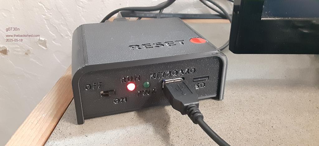 And am using a small TV instead of the other monitor. It has USB port in back so powering picomite from that. Turning on/off TV also turns on/off picomite. Plan on printing a VESA mount to attach to back. 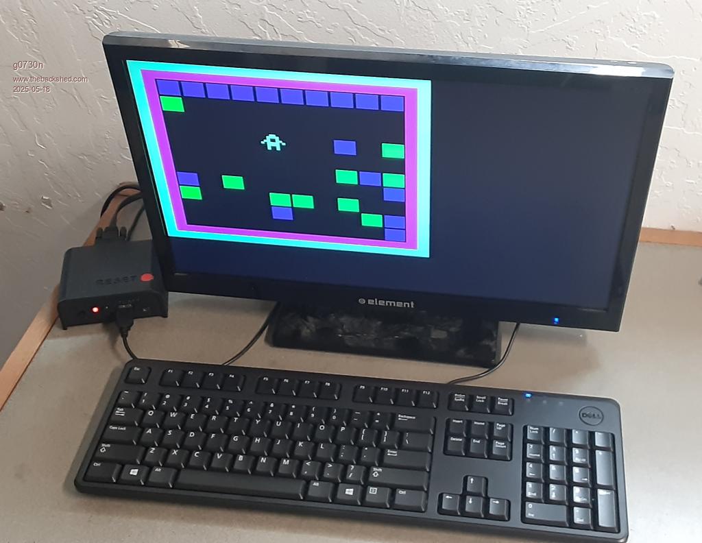 |
||||
| dddns Guru Joined: 20/09/2024 Location: GermanyPosts: 843 |
Very very nice results already after this short time! Congrats. What are you using for CAD? Edited 2025-05-18 04:26 by dddns |
||||
| lizby Guru Joined: 17/05/2016 Location: United StatesPosts: 3784 |
Very nice, neat job. Looks like a computer. PicoMite, Armmite F4, SensorKits, MMBasic Hardware, Games, etc. on FOTS |
||||
| stanleyella Guru Joined: 25/06/2022 Location: United KingdomPosts: 2807 |
if you start off with no pcb then strip board works 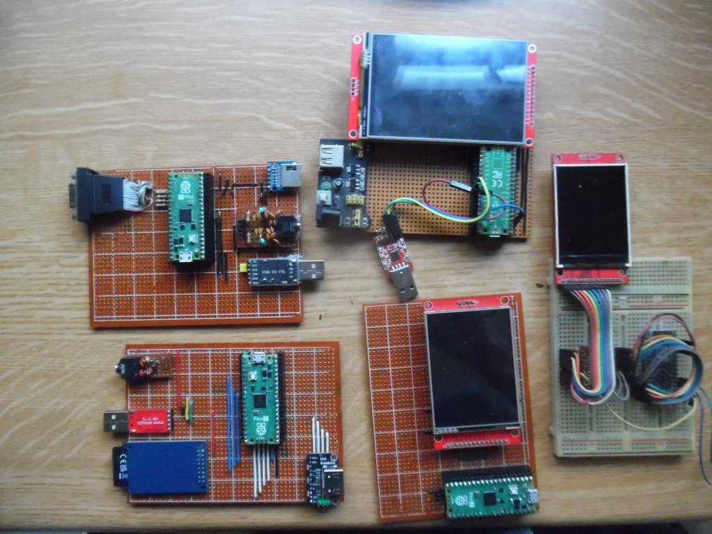 |
||||
| dddns Guru Joined: 20/09/2024 Location: GermanyPosts: 843 |
Great collection and very nice done but one type is missing :)) Does your mini keyboard still work?? Edited 2025-05-19 05:46 by dddns |
||||
| stanleyella Guru Joined: 25/06/2022 Location: United KingdomPosts: 2807 |
I use the hdmi usb and mini usb kb ok and mini wireless dongle kb ok. just a rant that you need a pcb to use mmb rpi when cheap strip board is quicker?? 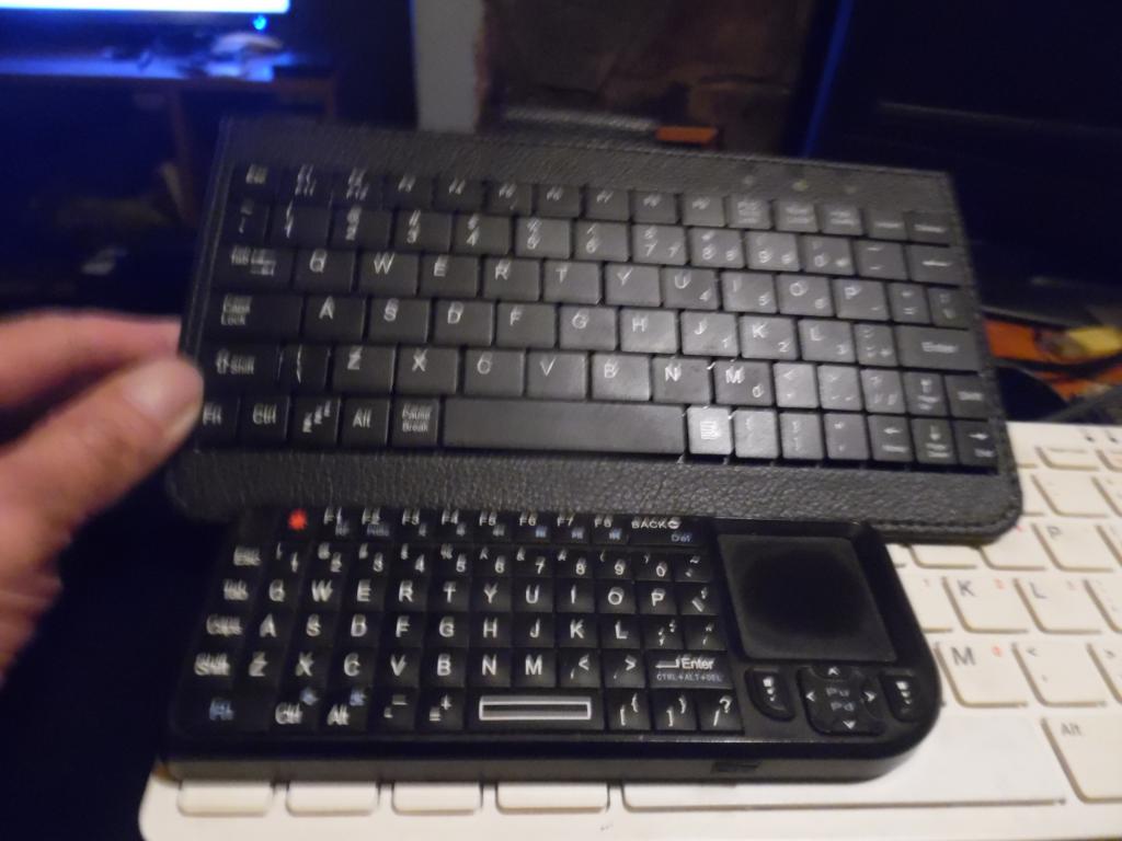 |
||||
| g0730n Newbie Joined: 14/05/2025 Location: United StatesPosts: 18 |
Fusion360 is what I use for designing all 3d models. Ideally I would use something open source such as freeCAD or Blender, but all my attemps to learn those hit a wall. Nice! Yeah the strip/protoboard is great especially with a first build. I have already decided to remove both piezo buzzers (they were too quiet when playing sounds or music, a single tone was audible though). I salvaged an old 3.5mm headphone jack from an old motherboard and now have full stereo sound on the tv with plenty of volume. And it sounds better  Yeah! That was what I was going for. I love the idea of being able to drop into a computer like this, program to my hearts content, and never worried about being distracted by a YT video or go down a rabbit hole of reading on a browser when I am looking something up. I printed out the full manual and have it on desk next to this computer haha. Also want to add a hub for 2 game controllers for games in the future. I have started designing a PCB for the next version. I will not finalize and order PCB until I have used the protoboard one for quite some time and have all the quirks figured out. I usually design on EasyEDA, and order PCB JLCPCB. I order the minimum of 5 boards. Ideally I will build all 5 and gift 4 to certain friends of mine who love stuff like this. A program I was thinking it would be cool to write for such a computer is a simple spreadsheet program. I use LibreOffice Calc heavily for my business stuff, but also some smaller sheets for personal record keeping. These smaller sheets I think would easily be readable/editable by a lightweight program. Then the possibilities of visualizing the data with MMBasic are endless! Thanks for all your interest and feedback on my build. This forum is awesome everyone is very friendly. God bless! Edited 2025-05-19 09:14 by g0730n |
||||
| stanleyella Guru Joined: 25/06/2022 Location: United KingdomPosts: 2807 |
rpi pico works well with stripboard.. it's vga and hdmi that don't fit. same with the board the author of the thread posted |
||||
| lizby Guru Joined: 17/05/2016 Location: United StatesPosts: 3784 |
I hear that. VegiPete wrote one for the CMM2. 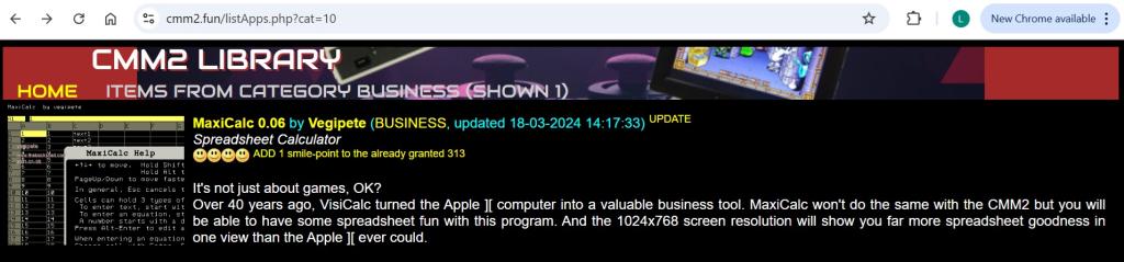 It's shown on the site, CMM2.fun, but the link to the zip file doesn't do anything. VegiPete still posts, so if you're interested in porting it to the PicoMite, you might be able to get the source from him. It probably wouldn't have run well on the early versions of the PicoMite, but possibly could do so now. PicoMite, Armmite F4, SensorKits, MMBasic Hardware, Games, etc. on FOTS |
||||
| g0730n Newbie Joined: 14/05/2025 Location: United StatesPosts: 18 |
That is awesome! I will look into that. Here is my current layout for the PCB version. Was trying to get all cables to plug into one side, and all user interaction (Reset Button, power switch, LED, and SD) on one side. Ended up being slightly larger than originally planned but it's still small  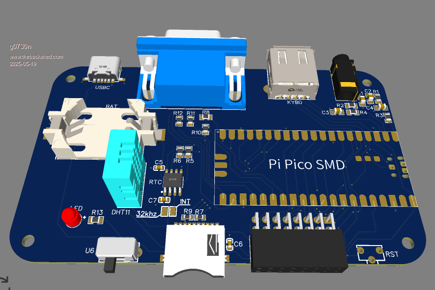 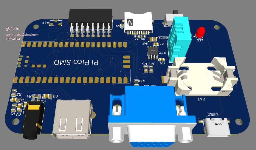 |
||||
| lizby Guru Joined: 17/05/2016 Location: United StatesPosts: 3784 |
Very tidy. Do you solder smd yourself, or would you have have JLCPCB do the whole job? You might want to have the DHT11 socketed, or use a DHT22 or AM2302. People here have reported that the DHT11 humidity sensor very quickly goes out of spec. I think TassyJim regularly bakes his in the oven to reset it (I'm not sure over what period of time or for how long at what temperature). DHT22 may not be much better. PicoMite, Armmite F4, SensorKits, MMBasic Hardware, Games, etc. on FOTS |
||||
| g0730n Newbie Joined: 14/05/2025 Location: United StatesPosts: 18 |
I hand Solder the SMD. It is very tedious, but have had success soldering TSSOP and down to 0402 components. If there is enough space I usually choose 0805 for more easy soldering. I am probably going to ditch the DH11 entirely for the BME280. It is I2C, and the placement on board puts it right next to I2C bus used for RTC. More expensive but way more accurate and also does atmospheric pressure. I wasn't sure if there was any support for it or if I could write my own driver, but looks like someone did it already ! https://www.thebackshed.com/forum/ViewTopic.php?TID=8362 I used DHT11 in current build because I have a handful of them in a box and saw there was already support baked into firmware. Edited 2025-05-19 10:59 by g0730n |
||||
| phil99 Guru Joined: 11/02/2018 Location: AustraliaPosts: 3293 |
Yes, all humidity sensors require occasional reviving, the DHT11 more so than any other. Some other humidity sensors have a built-in heater to do that. For the DHT11 the recommended method it to heat it in dry air at 50°C for at least two hours. This will remove moisture stuck to the sensing surface however other vapors can also stick to it resulting in a false high reading. Removing them may require heating to a higher temperature (70 to 80°C) for much longer. |
||||
| Page 1 of 3 |
|||||
| The Back Shed's forum code is written, and hosted, in Australia. | © JAQ Software 2026 |
