
|
|
Forum Index : Microcontroller and PC projects : converting PCF8523 RTC footprint to '3231
| Author | Message | ||||
| zeitfest Guru Joined: 31/07/2019 Location: AustraliaPosts: 683 |
Often pcbs provide pads for a PCF8523 RTC. I would rather a 3231 because, well, the purpose of a clock is to keep accurate time and although the PCF8523 is good in the short term, the 3231 is quite a bit better. So, looking at the pinouts, they both have similar 8-pin small outline packages. Both have connections out to to power, I2C, and the backup coin cell. Do you think a small adaptor pcb would be realistic ? It would have to use pads underneath to match the motherboard pads, then traces/vias/traces to the rewired pads on top matching the 3231. A bit tricky to do though. |
||||
| Mixtel90 Guru Joined: 05/10/2019 Location: United KingdomPosts: 8911 |
TBH I wouldn't use any board that had that as its choice of RTC. It says to me that they haven't thought it out and have cut costs to the bone - it would have cost nothing to have provided pads for a better RTC at the design stage. The option for an RTC hasn't really been considered. If you are retro-fitting into a piece of otherwise good equipment, then maybe, but otherwise no. Mick Zilog Inside! nascom.info for Nascom & Gemini Preliminary MMBasic docs & my PCB designs |
||||
| Andy-g0poy Regular Member Joined: 07/03/2023 Location: United KingdomPosts: 85 |
If you are really desperate to use the 3231, and I'm assume that you mean a 3231 module and not the raw chip. the the simple method would be to fit a double row header on the new module and wire-wrap / bodge wire the pins needed. Andy |
||||
| zeitfest Guru Joined: 31/07/2019 Location: AustraliaPosts: 683 |
I saw this pico feather future add-on so was wondering. Low-cost but Adafruit can be a bit idiosyncratic though. Still looking for simple pico2 + sdcard + good RTC module  |
||||
| Mixtel90 Guru Joined: 05/10/2019 Location: United KingdomPosts: 8911 |
Any use? 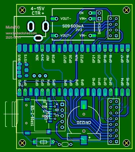 Mick Zilog Inside! nascom.info for Nascom & Gemini Preliminary MMBasic docs & my PCB designs |
||||
| zeitfest Guru Joined: 31/07/2019 Location: AustraliaPosts: 683 |
That looks very nice ! [ Give me a chance to work through the detail yet ]  so far- I'd put 1uF and 100nf capacitors on the SD socket power line to catch blips ed- and a I2C socket (Stemma / Qwiic) somewhere Edited 2025-06-17 11:34 by zeitfest |
||||
| Volhout Guru Joined: 05/03/2018 Location: NetherlandsPosts: 5931 |
Hi Mick, - widen the 3.3V trace. The S09 is 600mA capable, one may use it... - the RUN switch, put a 10n cap to ground to avoid noisy resets. I support your design choice for the S09 buck-boost regulator, but personally I would have gone for a buck regulator, with wider input range, maybe even a 5V one, and supply 5V at one of the pin headers. Too often I find this 5V useful. (like with the DAC output (thread about R-2r ladder DAC) for Nimue to test LED's) 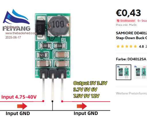 Volhout Edited 2025-06-17 16:23 by Volhout PicomiteVGA PETSCII ROBOTS |
||||
| Mixtel90 Guru Joined: 05/10/2019 Location: United KingdomPosts: 8911 |
Just playing again this morning... 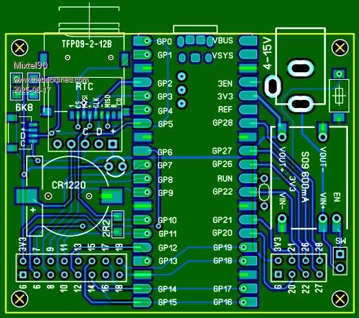 Quite a bit of tidying up and rearranging. Note that the USB socket can't power the Pico as the switcher is disabled. You will need to power via the barrel jack while programming so there will be two leads involved. :) Also, you can't power stuff via that connector, so it won't be suitable for USB Host mode. I picked the S09 because a) it's stupidly cheap and easily available and b) I already have a macro for it because I have some. :) It also sits flat on the board, which may be useful. That looks like a nice one though. :) I've reverse-engineered the S09. In theory (untested) you can change the feedback resistor for a 250K pot + 82K series resistor and get 3-10.5V variable out of it. :) I just don't have a 250K LIN pot to hand. Edit: (You should know me by now, Harm. :) No 5V on the GPIO connectors because I ran out of pins and it would mean making the board bigger. lol It would have been easy enough to use a 5V S09 and powered the Pico switcher from that, but I don't really like cascading switchers, although this combination seems to work. I powered my PicoGAME HDMI from one to test it.) . Edited 2025-06-17 18:20 by Mixtel90 Mick Zilog Inside! nascom.info for Nascom & Gemini Preliminary MMBasic docs & my PCB designs |
||||
| The Back Shed's forum code is written, and hosted, in Australia. | © JAQ Software 2026 |
