
|
|
Forum Index : Microcontroller and PC projects : The S09 buck/boost converter
| Author | Message | ||||
| Mixtel90 Guru Joined: 05/10/2019 Location: United KingdomPosts: 8911 |
Is this of interest to anyone? They are very cheap on AliExpress and are quite versatile. I've been reverse engineering it and it's a textbook SEPIC converter. 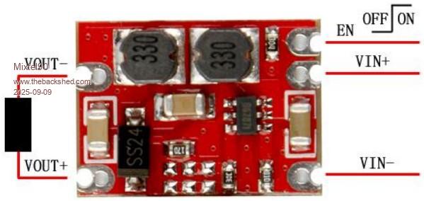 The maximum ratings for the S09 are not those of the MT3608 chip used. They are restrictions placed by the ancillary components and heatsink area available. A number of voltage variations are advertised. These vary according to the value of the feedback resistor used. This is the resistor closest to the centre of the board, where it is the most difficult to get to, of course! Values used are: Vout Rf E96 marking 3V3 91K 91B 4V2 121K 09D 5V0 147K 17D 9V0 280K 44D 12V 374K 56D We know that the internal reference is 0.6V and it is across 20K so it is quite possible to create customised voltages, of course: Rf = 20000 * ((Vout/0.6) -1) and variable voltage: Vout = 0.6 * (1+ (Rf/20000)) Using a 250K pot in series with 82K should give an output of 3V to 10.5V. I have concerns regarding the EN input. The module has a 300K series resistor from this pin, probably to protect it. However, this forms a voltage divider with a 100K turn-off resistor and the maximum input to switch on the converter can be as high as 1V5. This would mean that you might need 6V to enable it. As the maximum input voltage for the chip's input and EN inputs is 26V it would be fine to short the series resistor out providing the maximum input voltage would be Vin. The SEPIC configuration isn't bad, but efficiency is only about 75% and it's rather sluggish. Best used for loads that only change relatively slowly. Mick Zilog Inside! nascom.info for Nascom & Gemini Preliminary MMBasic docs & my PCB designs |
||||
Quazee137 Guru Joined: 07/08/2016 Location: United StatesPosts: 603 |
I use a few like this using the enable with a rc delay to drive relay modules from ESP-01. Keeps relays from chattering at main power on. Also with the micromites with inputs switching to outputs. Here is was the 4 relay modules. Quazee137 |
||||
| dddns Guru Joined: 20/09/2024 Location: GermanyPosts: 843 |
Hello Mixtel, this converter can handle 600mAh output which is too weak for my taste. There are similar once with 3A and a poti which could be replace by two resistors at the same price level.. |
||||
| Mixtel90 Guru Joined: 05/10/2019 Location: United KingdomPosts: 8911 |
The three unequipped component positions are connected across Rf. The first one is in series with the other two in parallel. It might be possible to have some fun with these. The top side of the first position is connected to Vout+ and the top sides of the remaining two go to FB on the chip. It might be slightly easier to connect to these rather than the Rf position when customising the voltage. Component values aren't the same as the data sheet for the chip, which is a little unusual for a cheap Chinese module. I wonder if the original design was for something in particular? That might make sense of the 300K EN resistor. E.g. something powered from a 7.2V battery and using the resistor to disable the supply at 5 or 6V. The E48 series resistors indicate that the design was intended to be fairly accurate. Mick Zilog Inside! nascom.info for Nascom & Gemini Preliminary MMBasic docs & my PCB designs |
||||
| The Back Shed's forum code is written, and hosted, in Australia. | © JAQ Software 2026 |
