
|
|
Forum Index : Microcontroller and PC projects : GAP2 - just an idea
| Page 1 of 2 |
|||||
| Author | Message | ||||
| Mixtel90 Guru Joined: 05/10/2019 Location: United KingdomPosts: 8964 |
I was inspired by the new WeAct board so I thought of this. I probably won't build it myself, but if anyone wants the gerbers I'll finish the development off. 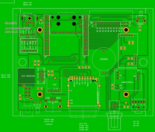 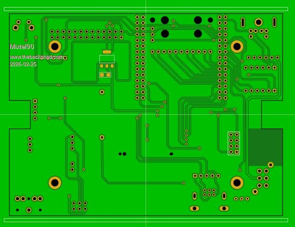 The Adafruit DVI breakout board appears to *just* fit between the connectors for the WeAct. I can't verify this as I haven't got a WeAct module. It saves having to solder an HDMI socket though. :) There's nothing on the edges of the module, you could take a bit off each side with a file or something. You get a dim red "standby" LED while it's off and a user-controlled green one while it's on. You can build it in two ways: USB (the default) - Power is supplied via the CP2102 module, which is also the terminal connection. The USB-C on the WeAct is for an external passive USB hub. STND - using standard HDMI firmware. A PS2 keyboard socket is fitted instead of the CP2102 module and power is supplied via the USB-C on the We-Act. There's a proper socket for a WII controller, but the USB version could also use USB controllers. The board is designed to fit the cheap Hammond RM2015 enclosure, like a small CMM2. This is only an idea at present. Mick Zilog Inside! nascom.info for Nascom & Gemini Preliminary MMBasic docs & my PCB designs |
||||
| lizby Guru Joined: 17/05/2016 Location: United StatesPosts: 3811 |
I like it. I will definitely order a set if/when you provide the gerbers. That Adafruit HDMI/DVI module ($1.95 plus shipping) is a brain-saver--as I find all the other little modules to be. ~ Edited 2026-02-25 05:04 by lizby PicoMite, Armmite F4, SensorKits, MMBasic Hardware, Games, etc. on FOTS |
||||
| Mixtel90 Guru Joined: 05/10/2019 Location: United KingdomPosts: 8964 |
Can you measure the distance between the sockets on the WeAct if you have one? It would be interesting to see if I've estimated correctly. :) I really need to check that it works out vertically too. It should do. Oh, one other thing, there's no Line Out for audio, only headphones. A resistor (which can be disconnected) mixes some of the left and right channels to form a more central image. I just hope the audio section is quiet enough! The problem is that all the audio modules have the gain far too high by default. In this case we need hardly any gain. Edited 2026-02-25 05:29 by Mixtel90 Mick Zilog Inside! nascom.info for Nascom & Gemini Preliminary MMBasic docs & my PCB designs |
||||
| lizby Guru Joined: 17/05/2016 Location: United StatesPosts: 3811 |
I have 15 tenths of an inch between the outer pins on the rows. That is, I can plug a 16-pin female header across them--1-1/2" pin to pin. PicoMite, Armmite F4, SensorKits, MMBasic Hardware, Games, etc. on FOTS |
||||
| PhenixRising Guru Joined: 07/11/2023 Location: United KingdomPosts: 2002 |
Mick, Was it yourself or Voluout who recommended VGA over HDMI for robustness? My experience with many monitors, many PCs and many cables; if I so much as sneeze, my HDMI signal breaks/makes. Anyone else experiencing this? I really like the VGA of the CMM2; Screw retainers  |
||||
| PhenixRising Guru Joined: 07/11/2023 Location: United KingdomPosts: 2002 |
Mick, Was it yourself or Volhout who recommended VGA over HDMI for robustness? My experience with many monitors, many PCs and many cables; if I so much as sneeze, my HDMI signal breaks/makes. Anyone else experiencing this? I really like the VGA of the CMM2; Screw retainers Edited 2026-02-25 11:33 by PhenixRising |
||||
| Mixtel90 Guru Joined: 05/10/2019 Location: United KingdomPosts: 8964 |
Lizby: It appears to be an interference fit in the gap! I think I'd recommend just sanding a touch off the outer edges of the Adafruit module, just to allow for tolerances in the thickness of the connectors and solder joints. It won't weaken the module in any way. Phenix: A through-hole HDMI connector with the four lugs soldered to through-plated pads in FR4 PCB is virtually impossible to remove without damaging something - difficult even with a hot plate and heat gun. I *always* use this type of connector as even a stiff HDMI lead won't pull the connector off. The other thing is that you need to solder the data pins properly. You need clean pads and pins and use flux to ensure that the solder flows into the microscopic area between the pin and the pad. Since I started using my current technique I've not had any problems, even with HDMI leads that are more or less supporting the complete board on that connector. :) Remember that the standard HDMI connector is a domestic produce and the D connectors are light industrial. They are for different markets really. the high density D15 connector was adopted for VGA so it makes sense to use it on the CMM2, even though that is a domestic product. You could equally well have used an RJ6 or RJ8 connector at the CMM2 end - they work well over any sane distance, use cheaper cable and use less PCB area. :) Mick Zilog Inside! nascom.info for Nascom & Gemini Preliminary MMBasic docs & my PCB designs |
||||
| PhenixRising Guru Joined: 07/11/2023 Location: United KingdomPosts: 2002 |
Been looking at these |
||||
| PhenixRising Guru Joined: 07/11/2023 Location: United KingdomPosts: 2002 |
Mick, didn't you already do a Picomite design with RJ45 VGA? |
||||
| Mixtel90 Guru Joined: 05/10/2019 Location: United KingdomPosts: 8964 |
Oh, probably. :) I've done so many I lose track... I rather like RJ connectors as they are quite easy to use and are available very cheaply. For VGA you only have 6 essential connections: R,G,B.HS,VS & GND. RJ 45 is good because each of R,G & B can have GND twisted with it, then twist the synchs. I got some similar adapters ages ago. I tested them over about 10m of CAT5 but I only had 640x480 at the time. Mick Zilog Inside! nascom.info for Nascom & Gemini Preliminary MMBasic docs & my PCB designs |
||||
| PhenixRising Guru Joined: 07/11/2023 Location: United KingdomPosts: 2002 |
I plan to use RJ45s to bring my DIO from the PicoMite to SSR racks. I don't mind them for fixed installations. I was recently called out to Deepsea Technologies in Bromborough (impressive) who had just brought a machine over from the states. They had intermittent problems and couldn't figure it out because the machine was fine before they shipped it. Wouldn't you know, my favourite (NOT) Beckhoff TwinCAT/EtherCAT  Long story short; whoever disconnected the console had evidently yanked on the EtherCAT cable (RJ45) and broke the tab off. On this end, they'd just shoved the plug in and assumed it would be OK.  The jolt had also messed up the base-unit socket (solder joint?) which is a sealed unit and so we had to find a replacement. The jolt had also messed up the base-unit socket (solder joint?) which is a sealed unit and so we had to find a replacement.Yeah that inexpensive little connector became very expensive. But from the PicoMite to SSRs and opto-couplers with colour-coded cabling...I like it |
||||
| lizby Guru Joined: 17/05/2016 Location: United StatesPosts: 3811 |
Any progress towards the gerbers? PicoMite, Armmite F4, SensorKits, MMBasic Hardware, Games, etc. on FOTS |
||||
| Mixtel90 Guru Joined: 05/10/2019 Location: United KingdomPosts: 8964 |
I'm still playing with the design a bit. I've been changing the power arrangement so that the power button works properly in both PS2 and USB modes. Increased the size of the regulator heatsink area a bit. Quite a bit of trace tidying and added component values. Added I2c pullups. Made 4 of the resistors through-hole in case someone wants to do some testing of different values. Quite a bit now I look back on it. :) The circuit diagram is still all in my head. Nothing written down. Gerbers shouldn't be long now. I need to have a further visual check (it helps to turn off the ground planes, I find), do a DRC and put mask on the vias yet. Just a bit more text, including the options settings, too. Mick Zilog Inside! nascom.info for Nascom & Gemini Preliminary MMBasic docs & my PCB designs |
||||
| lizby Guru Joined: 17/05/2016 Location: United StatesPosts: 3811 |
Resistors for what through-hole, if I may ask? PicoMite, Armmite F4, SensorKits, MMBasic Hardware, Games, etc. on FOTS |
||||
| Mixtel90 Guru Joined: 05/10/2019 Location: United KingdomPosts: 8964 |
The standby LED brightness Left-right blending for the headphones Left and right maximum audio level for the headphones The LED brightness will depend on your LED sensitivity The left and right max audio level will also give a bit of control over the balance for people like me who are deaf in one ear The audio blend is a personal thing. There is the option of disconnecting the resistor with a jumper too now. Mick Zilog Inside! nascom.info for Nascom & Gemini Preliminary MMBasic docs & my PCB designs |
||||
| lizby Guru Joined: 17/05/2016 Location: United StatesPosts: 3811 |
Any progress toward gerbers? PicoMite, Armmite F4, SensorKits, MMBasic Hardware, Games, etc. on FOTS |
||||
| Mixtel90 Guru Joined: 05/10/2019 Location: United KingdomPosts: 8964 |
I've been getting the BOM and a bit of a manual together, while doing final tweaks to the board. Currently I'm doing the circuit diagram - which comes in handy if something doesn't work. :) The board is, providing I don't find any errors while doing the circuit, probably done now. There have been changes to the layout to, hopefully, minimise noise on the audio. You can also select two different crossfeed levels or none using a jumper. Better than solder blobs here. Mick Zilog Inside! nascom.info for Nascom & Gemini Preliminary MMBasic docs & my PCB designs |
||||
| lizby Guru Joined: 17/05/2016 Location: United StatesPosts: 3811 |
At under $6 per try, I'd be happy to take the chance and submit it right now. Nothing significant is lost if I have to submit it again. (I totally botched a RP2350-Zero PCB recently--oh, well, fixed (I hope) and resubmitted.) PicoMite, Armmite F4, SensorKits, MMBasic Hardware, Games, etc. on FOTS |
||||
| Mixtel90 Guru Joined: 05/10/2019 Location: United KingdomPosts: 8964 |
That can be arranged. :) Gerbers.zip . Edited 2026-03-03 05:33 by Mixtel90 Mick Zilog Inside! nascom.info for Nascom & Gemini Preliminary MMBasic docs & my PCB designs |
||||
| lizby Guru Joined: 17/05/2016 Location: United StatesPosts: 3811 |
Ordered, thank you. Board price bumped to $4, engineering fee $4 added, shipping up to $7+ ("slow boat"); total $17. If the WeAct board, the HDMI output, and the RTC work it's a great bargain to me. If it's working, I'll be happy to ship a couple to you. PicoMite, Armmite F4, SensorKits, MMBasic Hardware, Games, etc. on FOTS |
||||
| Page 1 of 2 |
|||||
| The Back Shed's forum code is written, and hosted, in Australia. | © JAQ Software 2026 |
