
|
|
Forum Index : Microcontroller and PC projects : Stepper Project
| Page 1 of 22 |
|||||
| Author | Message | ||||
Bryan1 Guru Joined: 22/02/2006 Location: AustraliaPosts: 2155 |
G'day Guy's, Last week got 3 stepper boards and 2 each of the stepper driver chips and as I have got one of Peter's big 2350B boards so first job was getting my 3.5" touch screen working again. Tried everything and just had no luck with a 2350B board at all with the LCD screen just flickering so decided to setup my 2040 zero mounted on one of Mixtels boards which fits on my breadboard nicely and put RP2040 V6.02.00 on the zero. Yesterday had big think about it and drew the connections on a sheet of paper and this morning wired it all up only to find the same. Now looking on my Ali purchase it did state the lcd was a ILI9341 so with the zero test had the same flickering problem so just set it up for later. Reading thru the pico manual it came flooding back the big problem I had before was the MISO pin on the lcd must not be connected and sure enough clearing the options and going with the ILI9488 the GUI TEST LCDPANEL came up with the bubbles  also got the touch and SDCard working. also got the touch and SDCard working.> option list PicoMite MMBasic RP2040 V6.02.00 OPTION SYSTEM SPI GP2,GP3,GP4 OPTION COLOURCODE ON OPTION CPUSPEED (KHz) 200000 OPTION LCDPANEL ILI9488, LANDSCAPE,GP5,GP6,GP7 OPTION TOUCH GP9,GP10 GUI CALIBRATE 0, 3948, 3867, -1294, -872 OPTION SDCARD GP8 So in the morning I will rewire the big board backup with the LCD and then wire up one of the stepper boards and see if I can get the first stepper moving Regards Bryan |
||||
| Volhout Guru Joined: 05/03/2018 Location: NetherlandsPosts: 5994 |
Hi Bryan, Good you found it. Good luck with the steppers. I planned to suggest another LCD type. The 2.1, 2.4, 2.8 and 3.2 inch where 9341 (I own those). Larger sizes typically use a different chip (i.e. 9488) and more pixels. Volhout PicomiteVGA PETSCII ROBOTS |
||||
| Bryan1 Guru Joined: 22/02/2006 Location: AustraliaPosts: 2155 |
Decided it wouldn't take long and when I looked at the sheet with the pinouts for the 2350B board I did find they corresponded with the setup I had on the 2040 zero So just had to change a few pin assignments and had the LCD going on the big board where doing the GUI TEST LCDPANEL came up with the bubbles straight away but like before with my fun with calibrating the touch where after the second touch it went to error so thought as the tummy bones are complaining that's a job for the morning. Regards Bryan |
||||
| Bryan1 Guru Joined: 22/02/2006 Location: AustraliaPosts: 2155 |
Ok got everything hooked but just keep getting errors The code OPTION EXPLICIT On error skip Stepper close Stepper Init 0.05, 150, GP22 setpin GP27, Dout setpin GP25, dout setpin gp26, dout const dir = "GP25" const steppin = "GP27" const enable = "GP26" const E_Stop = "GP22" const FEED_MAX = 6 const FEED_DEFAULT_ON = 2 const UNIT_MM = 2 Const STEP_FEEDRATE = 200 const PRIME_STEP_MM = 5 do RunStepper loop Sub RunStepper Stepper Axis X, GP27, GP25, GP26, 1, 800, 100, 100 Stepper Position X, 0.1 Stepper run 1 Stepper gc g1 x0 f100 Stepper gc g1 x100 f100 Stepper gc g1 x0 f100 end sub The error in MCCC RUN Stepper initialized - 100KHz timer active Warning: Soft limits not configured. Use STEPPER LIMITS to set working area. Stepper armed - executing buffered commands [33] Stepper Axis X, GP24, GP25, GP26, 1, 800, 100, 100 Error : Pin 42/GP24 is in use So tried GP27 RUN Stepper initialized - 100KHz timer active Warning: Soft limits not configured. Use STEPPER LIMITS to set working area. Stepper armed - executing buffered commands [33] Stepper Axis X, GP27, GP25, GP26, 1, 800, 100, 100 Error : Pin 32/GP27 is in use Now my idea is simply go forward 100 then back 100 and if the E-Stop is pressed stop the output |
||||
| Bryan1 Guru Joined: 22/02/2006 Location: AustraliaPosts: 2155 |
Ok Guy's the whole point of this project is to make a state machine so I can run my old Macson surface grinder. 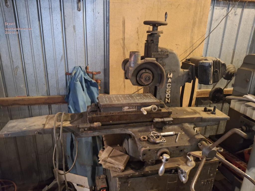 Now the inherent problem is with the Z axis on this machine where the lead screw has a heap of backlash and when setting the grinding wheel doing 2,000 RPM it tends to jump and I have already broken a grinding wheel trying to use this machine. This is where a ball screw can come into play for the Z axis so if needed a step by step can set the cut then the DRO on the screen can be set to zero where the predetermined cut is done. I do have a 2 pole 3 phase motor for this project and a Delta VFD so the motor can run off single phase and the best part the Delta VFD does have a serial interface where the hertz can be changed so the speed once calibrated can be dialed in using the G-code. Now the X axis rack and pinion drive and as it's only going back and forth I can machine the stepper mount off the original handle and fabricate up the securing mount for the stepper motor. The Y axis in operation is going to increment in steps every forward pass depending on the width of the grinding wheel. Now here is a pic of my test setup 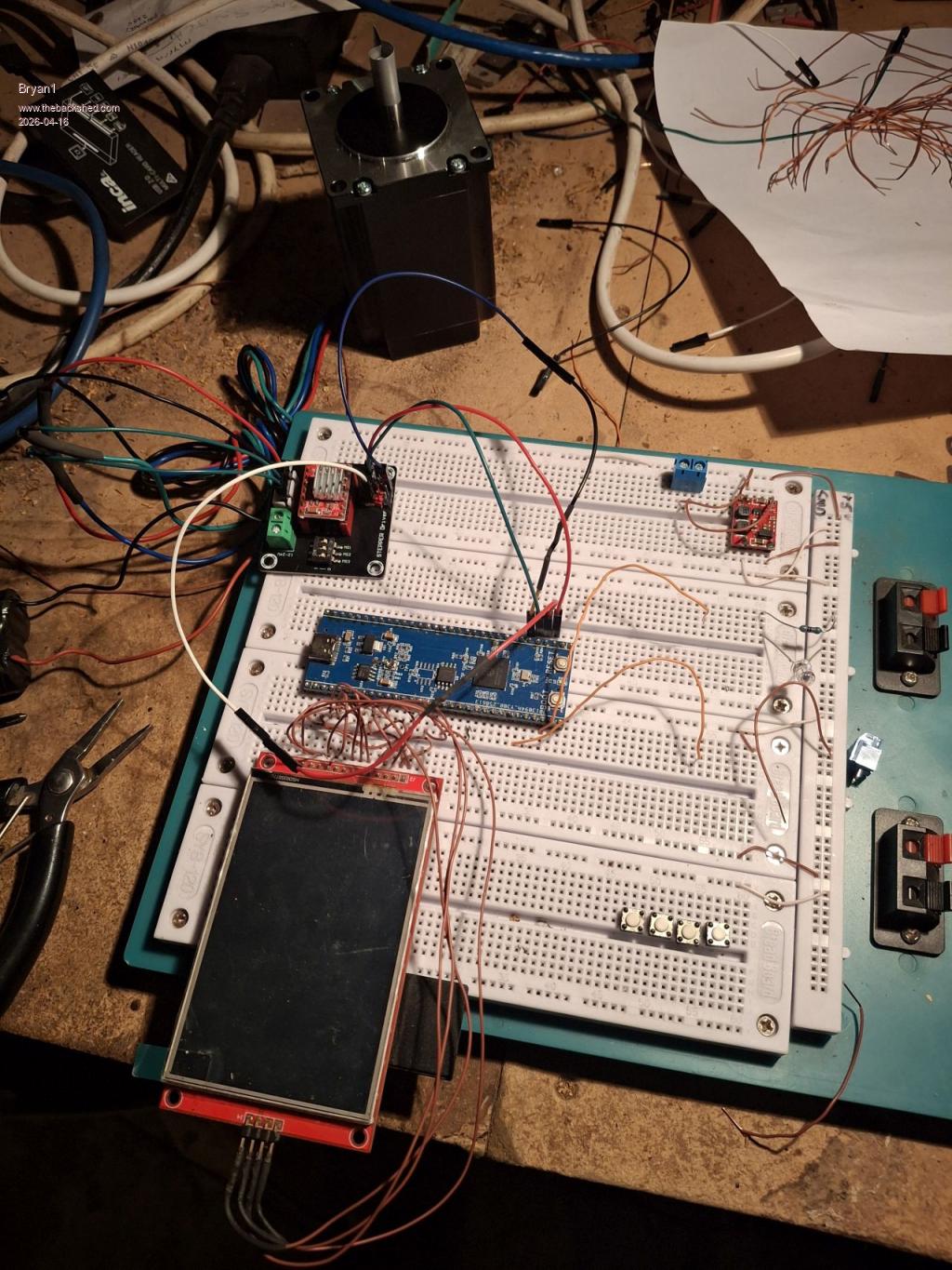 For now the 3.5" touch screen can do while the code is built up and as there are so many spare pins I do think a 9" touchscreen in 16 bit mode as reading in the manual today 16 bit can be done. I do need to order more dupoint cables for this project so no rush as I have been thinking about this project for a long time. Regards Bryan |
||||
| PhenixRising Guru Joined: 07/11/2023 Location: United KingdomPosts: 2000 |
Yeah that backlash needs fixed. No fun busting a grinding wheel  Those VFDs are fun, fun, fun I fitted one to an old Bridgeport knee mill and it runs beautifully. The original fwd/rev selector failed and it was £70 for a replacement. This was a good opportunity to try eliminating it altogether. The VFD + remote pendant was < £50. No need to mess with the belt/pulleys to change speeds now. Mine also has the serial interface but I prefer the external 0 to 10V analogue and fwd/rev-select option. It seems that most of these units have the option of VFD/Vector (FOC) modes. The Vector mode runs quieter. Pretty sure I could close the loop on this thing with encoder feedback to the PicoMite. It would be a bit of a dog compared to a true servo, due to the high rotor inertia and for continuous operation, I would need inverter-rated windings but there are many applications that are not so demanding. On two occasions over the past year, I have been called-out to a dead production line due to a failed motor starter. One was DOL and the other was star/delta. I didn't have time to order VFDs but I could've installed TWO (one as a spare) for similar cost. |
||||
| Bryan1 Guru Joined: 22/02/2006 Location: AustraliaPosts: 2155 |
Phonix back in the day when I worked as a heavy machinist I was starting my 30' planer motor when I went from star to delta a arc went over the the planer bed and one guy walking by copped it full on and he was gone.That 200 Kw motor was toast and that planer was never run again. Now as the steppers I have here are 2.4 Nm I don't think they will handle the current needed to run this surface grinder so I am thinking of getting somemore DM556 micro stepper modules off ebay. I did look at my old code in MMEdit that was still there and I'm sure you will remember that code Harm gave did run the stepper on my cnc. The problem is when I did that code GP numbers wern't needed so I do think this can done on 2040 without the new stepper code |
||||
| PhenixRising Guru Joined: 07/11/2023 Location: United KingdomPosts: 2000 |
Holy moly....that sounds to me like the planer wasn't grounded (earthed). Somehow a phase made the entire machine live and found a human pathway to ground. |
||||
| Bryan1 Guru Joined: 22/02/2006 Location: AustraliaPosts: 2155 |
na mate when I hit the star from delta switch a blue arc went across the planer and the poor worker copped it full on. Anyway the hole in the seconday on the motor I could stick 2 fingers in. |
||||
| mozzie Guru Joined: 15/06/2020 Location: AustraliaPosts: 403 |
G'day Brian, You have likely figured this out already but you don't need to set the GPIO pins to DOUT first, let the STEPPER AXIS command do it for you. Should stop the error messages. There is a version of that surface grinder in the shed here, we fitted a pneumatic cylinder under the grinder spindle head that takes the weight and backlash out of the leadscrew, a cheap regulator sets the pressure accordingly. Works so much better now Good luck. Regards, Lyle. |
||||
| PhenixRising Guru Joined: 07/11/2023 Location: United KingdomPosts: 2000 |
Used these for a similar application |
||||
| phil99 Guru Joined: 11/02/2018 Location: AustraliaPosts: 3321 |
They look like car bonnet struts. Might be a budget option from a wrecker? |
||||
| PhenixRising Guru Joined: 07/11/2023 Location: United KingdomPosts: 2000 |
good idea but....It's nice if they are adjustable |
||||
| Bryan1 Guru Joined: 22/02/2006 Location: AustraliaPosts: 2155 |
As this surface grinder is fully manual my idea of automating it does make sense so the grinder is more efficient. Now going a damper on the Z axis could work but I already have a ball screw that is suitable to fit. I got this off an old Hercus cnc lathe and length wise it will fit easily. Now I commented out the pin setting code and tried again. Stepper initialized - 100KHz timer active Warning: Soft limits not configured. Use STEPPER LIMITS to set working area. Stepper armed - executing buffered commands [33] Stepper Axis X, GP27, GP25, GP26, 1, 800, 100, 100 Error : Pin 32/GP27 is in use Now I commented out the const for the and got the same error. On error skip Stepper close Stepper Init 0.05, 150, GP22 'setpin GP27, Dout 'setpin GP25, dout 'setpin gp26, dout 'const dir = "GP25" 'const steppin = "GP27" 'const enable = "GP26" const E_Stop = "GP22" const FEED_MAX = 6 const FEED_DEFAULT_ON = 2 const UNIT_MM = 2 Const STEP_FEEDRATE = 200 const PRIME_STEP_MM = 5 do RunStepper loop Sub RunStepper Stepper Axis X, GP27, GP25, GP26, 1, 800, 100, 100 Stepper Position X, 0.1 Stepper run 1 Stepper gc g1 x0 f100 Stepper gc g1 x100 f100 Stepper gc g1 x0 f100 end sub So not sure whats going on here as I let Stepper Axis assign the pins Edited 2026-04-17 10:32 by Bryan1 |
||||
| Bryan1 Guru Joined: 22/02/2006 Location: AustraliaPosts: 2155 |
Ok sort of getting there as I setup more switch's for the axis limits and did get a message HW Limits are configured 'OPTION EXPLICIT On error skip Stepper close Stepper Init 0.05, 150, GP22 'setpin GP27, Dout 'setpin GP25, dout 'setpin gp26, dout 'const dir = "GP25" 'const steppin = "GP27" 'const enable = "GP26" const E_Stop = "GP22" STEPPER HWLimits GP23, GP21, GP20, GP19, GP18, GP17 Stepper limits X, 0, 200 Stepper Axis X, GP27, GP25, GP26, 1, 800, 100, 100 Stepper Position X, 0.1 Stepper run 1 do RunStepper loop Sub RunStepper 'Stepper run 1 Stepper gc g1 x0 f100 Stepper gc g1 x100 f100 Stepper gc g1 x0 f100 end sub Now after loading got this error RUN Stepper initialized - 100KHz timer active Warning: Soft limits not configured. Use STEPPER LIMITS to set working area. Hardware limit switches configured [19] Stepper limits X, 0, 200 Error : Axis not configured |
||||
| Bryan1 Guru Joined: 22/02/2006 Location: AustraliaPosts: 2155 |
Ok getting alot closer but getting a buffer full error  so commented out so only the one G-code line was there so commented out so only the one G-code line was there Stepper initialized - 100KHz timer active Warning: Soft limits not configured. Use STEPPER LIMITS to set working area. Hardware limit switches configured Stepper armed - executing buffered commands [39] Stepper gc g1 x100 f100 Error : G-code buffer full Now I've taken out the Y axis and gave it a good clean, now found there a dual nut setup for the backlash, now mounting the stepper is a pinch as I'll just put the leadscrew in my lathe and drill a 8mm hole where a couple of grub screws can be used for the drive. Then a simple mount can be made to clamp the stepper. I sort of figure once I can get the code working may aswell have the stepper under load and thats one axis sorted for the project. |
||||
| Bryan1 Guru Joined: 22/02/2006 Location: AustraliaPosts: 2155 |
Ok still having fun so I decided to setup my scope and set channel 1 to the step pin but haven't seen any action on the scope. It does seem it's going in an endless state Stepper initialized - 100KHz timer active Warning: Soft limits not configured. Use STEPPER LIMITS to set working area. Hardware limit switches configured Stepper armed - executing buffered commands Homing axes... The code OPTION EXPLICIT On error skip Stepper close Stepper Init 0.05, 150, GP22 'setpin GP27, Dout 'setpin GP25, dout 'setpin gp26, dout 'const dir = "GP25" 'const steppin = "GP27" 'const enable = "GP26" const E_Stop = "GP22" STEPPER HWLimits GP23, GP21, GP20, GP19, GP18, GP17 'Stepper limits X, 0, 200 Stepper Axis X, GP27, GP25, GP26, 0, 800, 100, 100 Stepper Position X, 0 Stepper run 1 'Stepper Position Home do RunStepper loop Sub RunStepper Stepper gc g28 x0 f100 Stepper gc g1 x100 f100 Stepper gc g1 x0 f100 end sub I have declared X position as 0 but the software is homing the axis in an endless loop |
||||
| phil99 Guru Joined: 11/02/2018 Location: AustraliaPosts: 3321 |
Just a guess after looking at the manual. As it appears to require hardware limits for all 3 axis perhaps you need to set software limits for all 3 as well, even though you are only using 1 axis. Might not work but easy enough to try. eg. STEPPER HWLimits GP23, GP21, GP20, GP19, GP18, GP17 Stepper limits X, 0, 200 Stepper limits Y, 0, 20 Stepper limits Z, 0, 20 Stepper Axis X, GP27, GP25, GP26, 0, 800, 100, 100 Stepper Position X, 0 Stepper run 1 'Stepper Position Home Here is your endless loop:- do Sub RunStepper is being called endlessly.RunStepper loop Maybe try without Do and Loop. Edited 2026-04-17 16:03 by phil99 |
||||
| Bryan1 Guru Joined: 22/02/2006 Location: AustraliaPosts: 2155 |
Ok did the Stepper Limits X, 0, 200 also the same for Y and Z now when I run it got the error Y axis wasn't set so commented Y and Z out. Now when I removed the do loop Stepper initialized - 100KHz timer active Warning: Soft limits not configured. Use STEPPER LIMITS to set working area. Hardware limit switches configured X axis limits: 0.000 to 200.000 mm (0 to 160000 steps) Stepper armed - executing buffered commands] Then it goes straight to the prompt so it exits the stepper program Now with the Do Loop Stepper initialized - 100KHz timer active Warning: Soft limits not configured. Use STEPPER LIMITS to set working area. Hardware limit switches configured X axis limits: 0.000 to 200.000 mm (0 to 160000 steps) Stepper armed - executing buffered commands [44] Stepper gc g1 x0 f100 Error : G-code buffer full Now I did put a Stepper Clear in so the buffer was reset OPTION EXPLICIT On error skip Stepper close Stepper Init 0.05, 150, GP22 'setpin GP27, Dout 'setpin GP25, dout 'setpin gp26, dout 'const dir = "GP25" 'const steppin = "GP27" 'const enable = "GP26" const E_Stop = "GP22" STEPPER HWLimits GP23, GP21, GP20, GP19, GP18, GP17 Stepper Axis X, GP27, GP25, GP26, 0, 800, 100, 100 Stepper limits X, 0, 200 'Stepper Limits Y, 0, 200 'Stepper Limits Z, 0, 200 Stepper Position X, 0 Stepper run 1 Stepper Clear 'Stepper Position Home do RunStepper loop Sub RunStepper 'Stepper gc g28 x0 f100 Stepper gc g1 x100 f100 Stepper gc g1 x0 f100 end sub Edited 2026-04-17 16:42 by Bryan1 |
||||
| PhenixRising Guru Joined: 07/11/2023 Location: United KingdomPosts: 2000 |
But with a coupling, correct? If not, the motor bearings will have a very short life-span. |
||||
| Page 1 of 22 |
|||||
| The Back Shed's forum code is written, and hosted, in Australia. | © JAQ Software 2026 |
