
|
|
Forum Index : Microcontroller and PC projects : Memory share with other devices
| Author | Message | ||||
| fred777 Regular Member Joined: 01/07/2021 Location: United KingdomPosts: 99 |
Hi there, would it be possible to feed parallel data to a pico running Memory share client from a non-pico device? For instance feeding external pixel data into the frame buffer? |
||||
| matherp Guru Joined: 11/12/2012 Location: United KingdomPosts: 11698 |
In theory - yes. You will need to read into Memory.c on github to understand the synchronisation protocol needed to start the transfer. Briefly it works like this: |
||||
| fred777 Regular Member Joined: 01/07/2021 Location: United KingdomPosts: 99 |
Thanks for the great explanation! If I understand this correctly, the clock speed after the setup is completed doesn’t matter much, right? Would it matter if the host would only send data occasionally? |
||||
| matherp Guru Joined: 11/12/2012 Location: United KingdomPosts: 11698 |
The client runs in a tight DMA/PIO loop waiting on the clock pulses so as long as the host stays in synch it should be OK |
||||
| fred777 Regular Member Joined: 01/07/2021 Location: United KingdomPosts: 99 |
Right, I’ll have a go at that. The idea is to feed the pixels from some stm mcus with attached camera directly into regions on the picomite’s screen buffer. And also gaining hdmi output along the way. |
||||
| fred777 Regular Member Joined: 01/07/2021 Location: United KingdomPosts: 99 |
int bus_width; // 4 or 8 data pins This suggests that a 4 bit link could also be possible. But how would I tell MMBasic to use 4 pins only? I tried only connecting GP0-3 but then get [31] Memory Share Client 1, 0, GP0, GP10, addr%, 38400 Error : Sync failed - remote end not responding |
||||
| matherp Guru Joined: 11/12/2012 Location: United KingdomPosts: 11698 |
MEMORY_SHARE_User_Manual.pdf |
||||
| fred777 Regular Member Joined: 01/07/2021 Location: United KingdomPosts: 99 |
Thanks, I was looking at an old version of the Manual. |
||||
| PhenixRising Guru Joined: 07/11/2023 Location: United KingdomPosts: 2033 |
Following with interest  |
||||
| fred777 Regular Member Joined: 01/07/2021 Location: United KingdomPosts: 99 |
This is absolutely fantastic. I hooked up my good old "Black Pill" STM32 board to the Pico2. Spend an hour or so to get it running and now the STM32 can do HDMI :-) The random output comes from the STM via the 4 bit Memory Share Link, while the time is displayed by the pico. And now any MCU can have Bitmapped VGA or HDMI output using the Picomite as external graphics adapter with just 5 (or 9) pins. Just for fun I'm going to try with a Picaxe and Basic Stamp. ' MMBASIC Picomite Memory share stop MODE 3 Dim addr% = MM.Info(writebuff) Memory Share Client 1, 0, GP0, GP10, addr%, 153000,4 Do Print @(100,100),Time$; Loop ' Mikroe Basic for ARM dim picoclock as sbit at GPIOB_ODR.B0 dim picobyteout as byte at GPIOA_ODR dim picobytein as byte at GPIOA_IDR main: picobyteout = 0 picobytein = 0 ' Set B0 as output GPIO_Digital_Output(@GPIOB_BASE, _GPIO_PINMASK_0) picobyteout = %00000001 ' Recog token for Pico picoclock = 0 UART1_Write_Text("Phase1") GPIO_Digital_Input(@GPIOA_BASE, _GPIO_PINMASK_2 or _GPIO_PINMASK_3) UART1_Write_Text("2") GPIO_Digital_Output(@GPIOA_BASE, _GPIO_PINMASK_0 or _GPIO_PINMASK_1) UART1_Write_Text("3") do byte1 = picobytein loop until byte1 = 9 Delay_ms 1 UART1_Write_Text("4") GPIO_Digital_Output(@GPIOA_BASE, _GPIO_PINMASK_0 or _GPIO_PINMASK_1 or _GPIO_PINMASK_2 or _GPIO_PINMASK_3) Delay_ms 5 UART1_Write_Text("56") picoclock = 1 byte1 = 0 while 1 picobyteout = byte1 picoclock = 0 picoclock = 1 byte1 = rand() wend 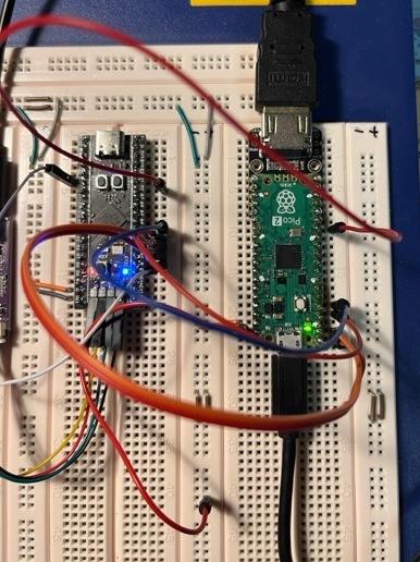 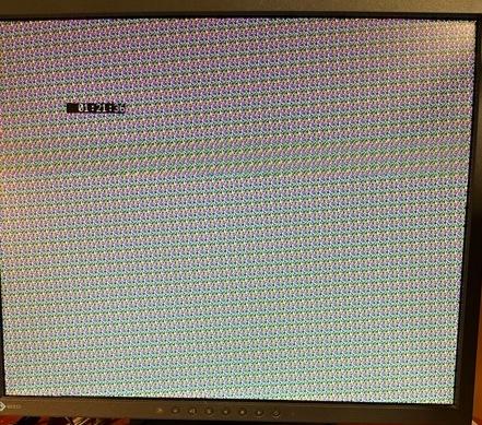 Edited 2026-06-11 02:53 by fred777 |
||||
| fred777 Regular Member Joined: 01/07/2021 Location: United KingdomPosts: 99 |
I love the Memory share function! Memory share 8 bit link between an AVR and Picomite, the avr can write directly into the Picomite's screen memory. Now even a good old 8 bit MCU can have a VGA/HDMI display without too much fuss :-) 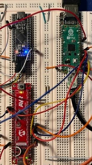 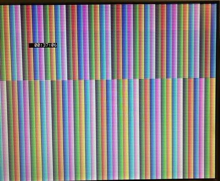 Edited 2026-06-18 23:32 by fred777 |
||||
| The Back Shed's forum code is written, and hosted, in Australia. | © JAQ Software 2026 |
