
|
|
Forum Index : Microcontroller and PC projects : Another easy-build one - PZ0
| Author | Message | ||||
| Mixtel90 Guru Joined: 05/10/2019 Location: United KingdomPosts: 8997 |
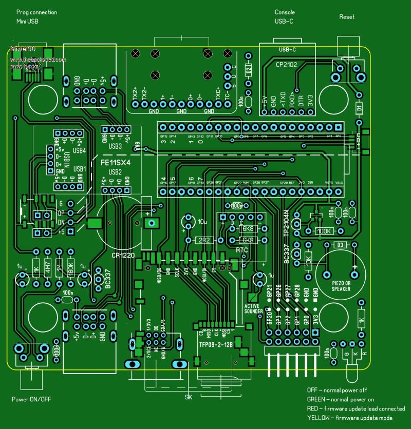 This is really a bit of a quick & dirty build for those who like to build stuff and want to play with HDMI and USB without buying a pre-assembled board. It's cheap and cheerful, for the most part. The most expensive components are the Pico 2 and the Adafruit HDMI/DVI breakout board. It's quite possible to build a basic version with only one surface mount device (the full size SD card socket), and even that's optional. The additional bits may involve SMD soldering. A couple of experimental bits. The power is toggled on and off using a little button and a mosfet (circuit found on Big Clive's channel). Option: The USB signals are disconnected using a clicky relay (remember those?) powered by the supply from the updating USB socket. The board can be built using either a full size SD card or a micro SD card and a WII socket. Firmware update connection can be done in one of three ways: 1 - direct connection to the Pico USB. 2 - connection to a mini USB updating socket and the hub disconnected using jumpers 3 - connection to the mini USB socket but with automatic hub disconnection as mentioned above. This should be particularly useful if the board is in an enclosure. I make no apology for using mini USB. It's by far the best small format USB connector for this job, being small, simple, rugged and relatively easy to hand solder. You don't need a breakout board for it. The only audio is a piezo buzzer or magnetic speaker on GP22. I've discovered that I rarely use the audio output. If I want to listen to music then I use headphones on my PC. I can't use speakers anyway. I threw in a GPIO connector for 8 uncommitted GPIO pins and a QWIC connector. Of course, it's smaller than 100x100mm to keep the PCB price down and it fits the RM2015S case. Incidentally, if you can't source that one the RM2015M is sometimes more readily available but it is 50mm high. That may not be a problem. Same fixings inside. I'll complete the design If I decide that I need one or if anyone else would like to build one. It's reached the stage where it needs component numbers, the schematic and BOM but it looks like it will probably work. :) Mick Zilog Inside! nascom.info for Nascom & Gemini Preliminary MMBasic docs & my PCB designs |
||||
| lizby Guru Joined: 17/05/2016 Location: United StatesPosts: 3838 |
I'm not sure I fully understand the design, but for hdmi usb, I feel what is needed is at least 4 and maybe 7 USB ports to accommodate Peter's new work. For me, PSRAM is also needed, but that may have to wait until it's available inexpensively on a 40-pin Picomite. PicoMite, Armmite F4, SensorKits, MMBasic Hardware, Games, etc. on FOTS |
||||
| Mixtel90 Guru Joined: 05/10/2019 Location: United KingdomPosts: 8997 |
My reasoning about PSRAM was that it's nice to have, and if Raspberry Pi had a module that had it then I'd use it. However they don't. That means that any design using modules rather than the home-unsolderable bare chip is totally dependent on a third party supplier and I want to get away from that if possible. The other modules aren't as important as they are long-established Chinese ones and are unlikely to disappear in the forseeable future. There are 4 USB ports on board (2 on the front and 2 on the back). You could piggy back an external hub from one of those or, if you short out a diode and the Pico can work that way, you also have direct access to the Pico's USB connection via the mini USB socket. As I said, this is basically a cheap quick and dirty. If you have the money to get JLCPCB to assemble better boards then that's fine, but you need to be able to sell or use the extra ones because of the minimum order. I could easily have used one of the RP2350 modules, and I still might, but that wasn't the target this time. It would certainly need a bigger PCB and possibly a bigger case. The modules are more expensive and there is a single manufacturer for each one - none of them as big as Raspberry Pi. There are all sorts of things I *could* have done, but this one is a compromise. Note that it is based on the Pico 2, so any device that is pin compatible and has the HSTX should work, even if it isn't currently available. :) Mick Zilog Inside! nascom.info for Nascom & Gemini Preliminary MMBasic docs & my PCB designs |
||||
| Mixtel90 Guru Joined: 05/10/2019 Location: United KingdomPosts: 8997 |
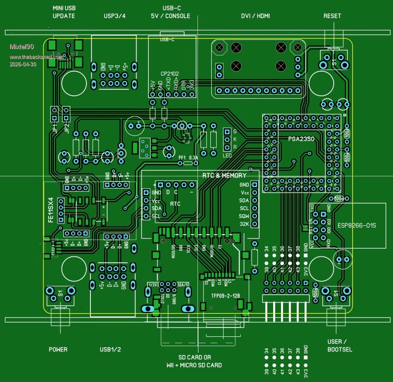 A very similar sort of thing, but this time using the PGA2350. I've retained most of the features and still kept the cost reasonably low and construction pretty easy, I think. There are few module options if you want PSRAM and built-in USB. The PGA2350 is probably one of the best but it does need a lot of soldering! By the time you take the connectors into consideration that's 128 soldered joints. :) Major changes: * PSRAM is present (enabled by GP47) * The GPIO pins GP34-GP43 give a better range of possibilities including (unless used for something else) I2C2, both SPI, both COM and four ADC. (System I2C is on I2C0 - GP32/GP33) * ESP8266-01S can optionally be fitted as the Pico 2 W isn't an option. It uses COM1 (GP44/GP45) and has its own supply regulator so isn't switched by the main mosfet. Instead, EN can be controlled by either GP46 or the 3V3 supply to enable it automatically. * Option to use the larger RTC module with CR2032 and memory on it * Bootsel available on the front, useful as a user input. * The HDMI connector can now be upside down! It sounds silly, but you can now fit it as a plug-in module so it can be moved between boards. It makes it more recyclable. Having it upside down means that it will still fit in the S enclosure. OPTION HDMI PINS has to be changed, obviously. There was no PCB width left for the LED, but it can still be fitted on flying leads and poked through the front panel above something else. Once again, it's at a fairly advanced design stage and *should* work, if anyone's interested. Mick Zilog Inside! nascom.info for Nascom & Gemini Preliminary MMBasic docs & my PCB designs |
||||
| PhenixRising Guru Joined: 07/11/2023 Location: United KingdomPosts: 2035 |
I see the deliberate mistake that you did to see if we were paying attention (sneaky)  "USP 3/4 |
||||
| Mixtel90 Guru Joined: 05/10/2019 Location: United KingdomPosts: 8997 |
Well, yeah... :) I bet that you didn't spot that some I2C wiring is missing though. :) There are a few changes and corrections to the layout already. It's in a state of flux. lol Mick Zilog Inside! nascom.info for Nascom & Gemini Preliminary MMBasic docs & my PCB designs |
||||
| PhenixRising Guru Joined: 07/11/2023 Location: United KingdomPosts: 2035 |
Question: Let's say I wanted to use the new USB-to-console-port communication method but without the actual USB sockets (direct connection). What would need to be done, here? |
||||
| Mixtel90 Guru Joined: 05/10/2019 Location: United KingdomPosts: 8997 |
It's not something I've considered. TBH I've not been keeping up with that and I don't know what it involves at all. Mick Zilog Inside! nascom.info for Nascom & Gemini Preliminary MMBasic docs & my PCB designs |
||||
| PhenixRising Guru Joined: 07/11/2023 Location: United KingdomPosts: 2035 |
A small detail that bothers me is that; at some point, the user needs to open the enclosure to change the battery. I have been looking at these: 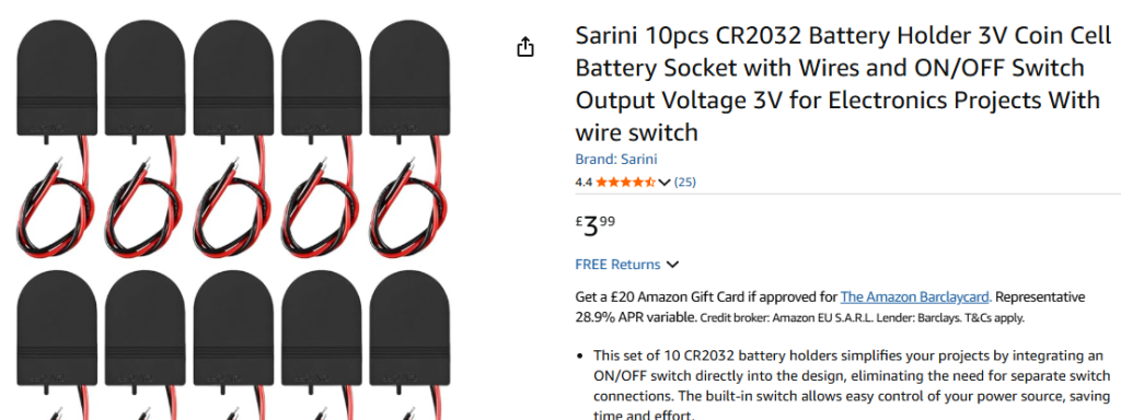 |
||||
| Mixtel90 Guru Joined: 05/10/2019 Location: United KingdomPosts: 8997 |
Those are fine. However, when did you last need to change the CR2032 on a PC motherboard? They do last a while. You can directly wire one of those holders to one of the little square RTCs as a good upgrade when its little yellow cell dies. :) Mick Zilog Inside! nascom.info for Nascom & Gemini Preliminary MMBasic docs & my PCB designs |
||||
| The Back Shed's forum code is written, and hosted, in Australia. | © JAQ Software 2026 |
