
|
|
Forum Index : Microcontroller and PC projects : Just a side project
| Page 1 of 2 |
|||||
| Author | Message | ||||
Bryan1 Guru Joined: 22/02/2006 Location: AustraliaPosts: 2155 |
Well guy's as I keep getting errors with my surface grinder project it is going to take Lyle to the rescue to finish it off. So now I as had that spare 3.5" ILI9488 LCD I hooked up with my zero board only to find the touch would fail and doing a research Phill gave a while ago pointed me at the spi lines well finally I got the touch calibrated > option list PicoMite MMBasic RP2040 V6.03.00RC14 OPTION SYSTEM SPI GP10,GP11,GP12 OPTION COLOURCODE ON OPTION CPUSPEED (KHz) 200000 OPTION LCDPANEL CONSOLE OPTION DISPLAY 26, 60 OPTION LCDPANEL ILI9488, LANDSCAPE,GP2,GP1,GP0,GP5 OPTION TOUCH GP4,GP3 GUI CALIBRATE 0, 4062, 4061, -840000, -866666 Now what I found was hitting enter in MCCC after I ran the program with Phill's code for the DS1820 thread. 50 Temp = 18.1°C 50 Temp = 18.1°C 50 Temp = 18.1°C 5 > mp = 18.1 > mp = 18.1° > 0p = 18.1 > mp = 18.1° > option list As for this project if I'm correct we switch the active rather than the neutral line on the AC a 12 volt relay is needed so a new PCB will be designed. Now my idea is as I have a 240 volt AC 30 watt heating belt that will cook a 25 litre fermenter so temperature control is needed. So using the DS1820 we can keep a 22-26 C range so the beer ferment goes smooth and lets face it US Aussies just love a beer where temperature controlled ferment is needed to get that right drop. Anyway thats my goal but honestly the PCB design will work for any temperature range we set it too with 2 relays that can switch AC loads to achieve the temperature ranges we need. Regards Bryan |
||||
| Mixtel90 Guru Joined: 05/10/2019 Location: United KingdomPosts: 8964 |
I cheat. :-) STC-1000 temperature controller. £3.80 from AE including the necessary temperature sensor. Individual isolated Heat and Cool relays rated for mains. Available for 12VDC, 24VDC or AC mains supply. I'm going to use two of these for controlling aquarium temperature. You configure the setpoint and the hysteresis, that's all you need. For heating only I will have the setpoint at 24.5°C and the hysteresis at 1°C. The heater then kicks in at 23.5°C (setpoint-hysteresis) and drops out at 24.5°C. The Cool contact will close at 25.5°C (setpoint+hysteresis) and drop out at 24.5°C. That makes it useful for either cooling fans or an overtemp alarm. Mick Zilog Inside! nascom.info for Nascom & Gemini Preliminary MMBasic docs & my PCB designs |
||||
| Bryan1 Guru Joined: 22/02/2006 Location: AustraliaPosts: 2155 |
Well I guess I'm having fun with Claude tonight as here is the code for upto 8 DS1820's to hook upto 8 relays on a 2040 zero with my ILI9488 TempControl_v1.zip So with meeting with Claude am I finally waking up to a world here writing MMBasic code is just asking Claude a few questions and the code is done. Gotta say for a guy deciding to have some shed beers after waiting 6 months getting to know Claude has been a eye opener for me. I did ask Claude to give me a sprint layout but it was a no go as it was a closed source so fun tomorrow in Sprint Layout making the board with a 2 relay option. Edited 2026-05-31 19:56 by Bryan1 |
||||
| PhenixRising Guru Joined: 07/11/2023 Location: United KingdomPosts: 2003 |
I wonder... Could Claude (or similar) come up with Gerber plots. SL6 can import Gerbers and then all that's left is to add the TH pads, etc. 🤔 |
||||
| Bryan1 Guru Joined: 22/02/2006 Location: AustraliaPosts: 2155 |
Yea I was hoping Claude would design the circuit for me but where will the fun go of designing the boards for review go but eh we can't ask AI to do everything can we. |
||||
| phil99 Guru Joined: 11/02/2018 Location: AustraliaPosts: 3321 |
Had a look at Claud's** code and it calls a DS18B20() Function that isn't included. You could add one from the "tempr not working" thread but MMbasic has it's own. TEMPR START GPxx,3 : Temp = TEMPR(GPxx) Print Temp The ",3" sets the resolution to 1/16°, ,2 = 1/8°, ,1 = 1/4° and ,0 = 1/2°. Lower resolutions convert faster. The example above shows TEMPR(GPxx) immediately following TEMPR START but it doesn't need to. You can put other code between to make use of the 600mS or so it takes to do a conversion. When reading multiple DS18B20s for maximum efficiency do all the TEMPR STARTs in a block, other code then all the TEMPR(GPxx)s in a block. eg for 4 sensors on pins 4 to 7 (GP2 to GP5) For n=4 to 7 : TEMPR START n,3 : Next ** Should we be using a capital "C" as claude isn't a person? Edited 2026-06-01 08:00 by phil99 |
||||
| Bryan1 Guru Joined: 22/02/2006 Location: AustraliaPosts: 2155 |
Ok I'm working with claude to try and get my slave zero on my OV7670 camera setup for I2C but keep getting errors. PicoMite MMBasic RP2040 V6.03.00RC14 OPTION SYSTEM I2C GP14,GP15 OPTION COLOURCODE ON OPTION CPUSPEED (KHz) 288000 Now I put the I2C SLAVE OPEN 0x30, 0, 256, i2c_int in a file and ran it[5] I2C SLAVE OPEN 0x30, 0, 256, i2c_int Error : Pin not set for I2C So why is this doing this when doing a list pins GP11 15 OFF GP12 16 OFF GP13 17 OFF GP14 19 Boot Reserved : SYSTEM I2C SDA GP15 20 Boot Reserved : SYSTEM I2C SCL GP16 21 OFF GP17 22 OFF GP18 24 OFF The I2C is setup and it should just work |
||||
| Bryan1 Guru Joined: 22/02/2006 Location: AustraliaPosts: 2155 |
Ok to explain this in more detail a few years ago I made up a piggyback Zero board for a OV7670 camera, today I finally brought it out to see if I could get it working. So to get started we just tried to get the zero slave to open but kept getting conflicts now it clearly states in the manual for I2C2 GP14 and GP15 are listed as suitable pins. this is the slave code ' OPTION EXPLICIT OPTION DEFAULT NONE CAMERA OPEN GP8, GP10, GP11, GP12, GP13, GP0 ' capture frame I2C OPEN 100, 1000 ' master mode, no SETPIN needed ' send chunks to display Zero I2C CLOSE Now before we get to I2C [5] Camera OPEN GP8, GP10, GP11, GP12, GP13, GP0 Error : Invalid display type claude did suggest to open on the slave zero I2C as a master so my camera open command is the same as the command in the manual CAMERA OPEN XLKpin, PLKpin, HSpin, VSCpin, RETpin, D0pin the XLK pin GP8, PLK pin GP10, HS pin GP11, VS pin GP13, D0 pin GP0 Regards Bryan |
||||
| phil99 Guru Joined: 11/02/2018 Location: AustraliaPosts: 3321 |
If you look at the Hardware Details page in the manual GP14 and GP15 are I2C channel 2. So all commands using System I2C on those pins need to start with I2C2. System I2C is always Open so trying to open or close it it wont work. Just use:- I2C2 WRITE addr, option, sendlen, senddata [,sendata ..] and I2C2 READ addr, option, rcvlen, rcvbuf As per Appendix B. Someone else will have to help with the camera. Edited 2026-06-02 16:54 by phil99 |
||||
| Bryan1 Guru Joined: 22/02/2006 Location: AustraliaPosts: 2155 |
While doing a search on the forum last night I did see the camera command was getting dropped from the 2040 so that may be my issue with the camera open command.  Today I will flash 6.00 on the zero and try again and see how that goes as once I can get the I2C working with the zero camera code one of my 2040W pic's is coming out so the real fun can start. Regards Bryan |
||||
| JanVolk Guru Joined: 28/01/2023 Location: NetherlandsPosts: 386 |
Bryan1, V6.02.02b0 PicoMiteV6.02.02B0.zip PicoMiteRP2040 no longer supports the CAMERA command. This therefore applies to version V6.03.00RC14 and later. Jan. |
||||
| Bryan1 Guru Joined: 22/02/2006 Location: AustraliaPosts: 2155 |
Yes I did put V6.3.00RC14 on the zero yesterday so after my caffine intake I will put an earlier version on and try it out. It does seem with the pace of improvement with the Pico one's old stock of parts may just need to use old software afterall the camera is just going to be setup looking at a water trough so in spring watching huge eastern brown and black snakes taking a drink will be a sight to see. I do have Starlink broadcasting wifi around the farm so connection issues for the 2040W won't be an issue. |
||||
| JanVolk Guru Joined: 28/01/2023 Location: NetherlandsPosts: 386 |
Bryan1, "It does seem with the pace of improvement with the Pico one's old stock of parts may just need to use old software afterall the camera is just going to be setup looking at a water trough so in spring watching huge eastern brown and black snakes taking a drink will be a sight to see." It is also better to observe the snakes from a safe distance. The latest RP2350 modules still support the CAMERA command in the current versions, but it has not yet been tested. Jan. |
||||
| Bryan1 Guru Joined: 22/02/2006 Location: AustraliaPosts: 2155 |
Ok loaded up V6.02.00 and got this > option list PicoMite MMBasic RP2040 V6.02.00 OPTION SYSTEM I2C GP14,GP15 OPTION COLOURCODE ON OPTION CPUSPEED (KHz) 280000 > C:\Users\Bryan\Documents\MMBasic Code\camera board.bas Uploading using: 'target port\COM13:115200 s\picomite Upload started NEW > AUTOSAVE N Progress: 1/16 Upload completed 1 Saved 261 bytes > Time taken: 1279mS RUN [5] Camera OPEN GP8, GP10, GP11, GP12, GP13, GP0 Error : Invalid display type So I had to fire up my laptop to get V6 and this was the result RUN [5] Camera OPEN GP8, GP10, GP11, GP12, GP13, GP0 Error : Invalid display type > option list PicoMite MMBasic RP2040 Edition V6.00.02 OPTION SYSTEM I2C GP14,GP15 OPTION COLOURCODE ON OPTION CPUSPEED (KHz) 280000 So I do think it's time to solder some pins on 2040 chip so I can have the LCD and the camera on the same pico. Now I did have the breadboard powered up and the zero connected to GP14, GP15 doing a I2C check came back with pin not set so this zero piggyback project can go in the bin as I think that is the problem. |
||||
| Bryan1 Guru Joined: 22/02/2006 Location: AustraliaPosts: 2155 |
Ok got a Webmite out and as I didn't have the Webmite Firmware got onto Geoff's Site and downloaded the manual. Loaded up V6.02.01 and did a option wifi with the Webmite on a 5 metre USB cable so it could get a line of sight. > option list WebMite MMBasic RP2040 Edition V6.02.01 OPTION COLOURCODE ON OPTION CPUSPEED (KHz) 200000 > option wifi "*****", "************" 10:27:50 Port: COM14 removed Disconnected 10:27:51 Port: COM14 inserted Connected to COM14 at 115200 PICOE6614104032 connecting to WiFi... Connected 192.168.1.29 > option list WebMite MMBasic RP2040 Edition V6.02.01 OPTION COLOURCODE ON OPTION CPUSPEED (KHz) 200000 OPTION WIFI Home, *********, PICOE6614104032 Now it's time for a caffine intake so more reading can get done and for once everything just worked.  Regards Bryan |
||||
| Bryan1 Guru Joined: 22/02/2006 Location: AustraliaPosts: 2155 |
Ok left the 2040W going all day and got telnet working nicely so a huge thanks to Geoff for including the links for teraterm also for the HTML links as it does bring back memories. When I type web ntp 9.5 both MCCC and teraterm show the data So my old idea of remote camera's around the farm has come back around and found it's just so easy to connect to the wifi meant a few hours designing up a new PCB 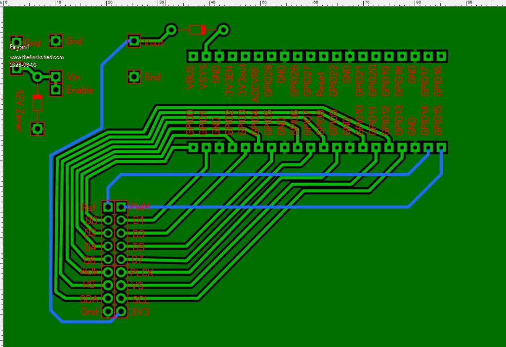 Still under development but managed to get all the connections on one side of the 2040W Now as this will be using batteries I do need to sort out the charging circuit as I have a few 5 watt solar panels to use which can go on each unit. As those S09's have a 15 volt input a 12 volt zener can go on so if in the event of the panels going open circuit the pcb won't be toast. So much thinking on the best way to get this done while waiting for my LCD boards to arrive. Regards Bryan Edited 2026-06-03 16:59 by Bryan1 |
||||
| Mixtel90 Guru Joined: 05/10/2019 Location: United KingdomPosts: 8964 |
I think the 15V input voltage limit of the S09 is only fixed by the input capacitor rating. The chip (assuming it meets the spec) is rated for up to 24V input. I suspect that if you remove the capacitor between the VIN- and VIN+ pins and replace it with a 10uF or 22uF cap (tantalum would be nice) with a higher voltage rating then you are in business. The EN input is also rated at up to 24V so no changes there. You need the cap as close to the chip as you can get it really. The SW pin of the mosfet is actually rated up to 30V so the spec sheet allows an absolute max of 26V on VIN+ and EN. Mick Zilog Inside! nascom.info for Nascom & Gemini Preliminary MMBasic docs & my PCB designs |
||||
| Bryan1 Guru Joined: 22/02/2006 Location: AustraliaPosts: 2155 |
Well I got my head around the charging circuit I think 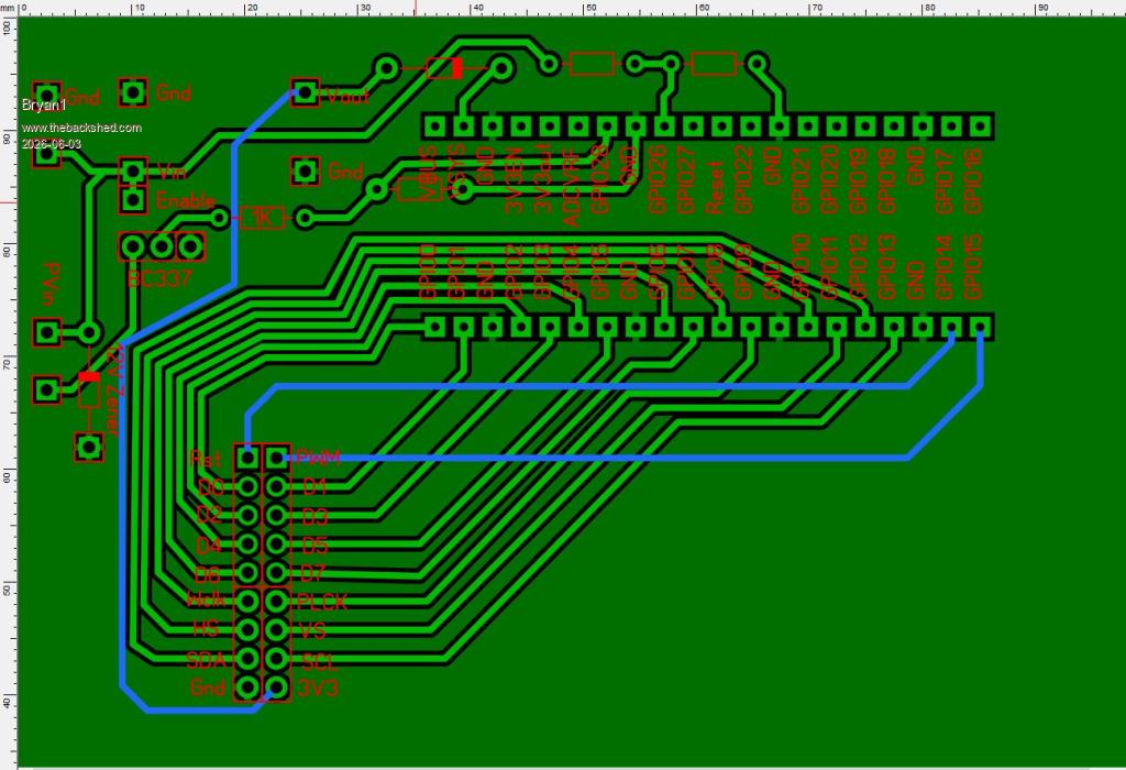 Now the lower 5.08mm connector is the PV input where it feeds into the collector of the BC337 transistor then 1K series and 22K to ground and GP28 is used to enable charging. Now when we want to measure battery voltage GP28 switch's off the BC337 so the voltage divider can measure the battery where GP26 is used. Off memory that lithium battery the the local battery guy made for had a 12 volt max input so by clamping the solar panel to 12 volts won't burn out the BMS. Regards Bryan |
||||
| Mixtel90 Guru Joined: 05/10/2019 Location: United KingdomPosts: 8964 |
The reason they used a 15V cap is almost certainly cost. The price rises rapidly above that and you are probably moving up a package size so it won't fit the same pads. Careful with the lithium. If it's not got protection on the pack (and it should have, including the charging circuitry) then fit some. Lithium cells don't usually fit into "12V", the closest is a 3S pack, at 3x3.7V = 11.1V and about 12V at max charge. For that you need a 3S charge and protection module so that the cells will balance their charge. Mick Zilog Inside! nascom.info for Nascom & Gemini Preliminary MMBasic docs & my PCB designs |
||||
| Bryan1 Guru Joined: 22/02/2006 Location: AustraliaPosts: 2155 |
Mick the local battery guy has served me for over 20 years now with my vehicle batteries and with price bang for buck trying to get the same battery at super cheap and those mobs is a heap more money. Now the guy did burn down his shed due to a battery fire and totally destroyed the shed, now when I asked him about it he was testing a Ebike battery went inside for a coffee and saw the flames then it was over. He does have a heap of knowledge on building packs so I will keep using him. Eh mate if you think that board is OK it can go off to JLCPCB and @ $3.50 the wait time is the expensive part as waiting for the slow boat of Aussie Post is getting longer. |
||||
| Page 1 of 2 |
|||||
| The Back Shed's forum code is written, and hosted, in Australia. | © JAQ Software 2026 |
