
|
|
Forum Index : Microcontroller and PC projects : Picomite VGA: VGA to HDMI-converter doesn't work
| Page 1 of 2 |
|||||
| Author | Message | ||||
| v.lenzer Senior Member Joined: 04/05/2024 Location: GermanyPosts: 131 |
Hi everyone! I happened to pick up a PCB for the PicoMite VGA on eBay. It was quick to assemble, and everything is running perfectly. I’m using an RP2350. Now I’ve finally been able to view your great graphics for the PicoMite VGA. Awesome! The file manager is excellent, too. My first program—an I2C scanner—worked right away. Next, I wanted to use my PC monitor (which has an HDMI input) as the display for the PicoMite. To do this, I bought a VGA-to-HDMI converter from AliExpress (https://de.aliexpress.com/item/1005008584694136.html?spm=a2g0o.order_list.order_list_main.53.6d9b5c5fNZ8vjp&gatewayAdapt=glo2deu). Unfortunately, it doesn't work at all. Has anyone here tried getting a picture using a VGA-to-HDMI converter like this? Here are my settings: PicoMiteVGA MMBasic RP2350A Edition V6.03.00B2 OPTION SYSTEM I2C GP0,GP1 OPTION AUTORUN ON OPTION COLOURCODE ON OPTION KEYBOARD GR OPTION HEARTBEAT OFF OPTION RESOLUTION 640x480 @ 252000KHz OPTION SDCARD GP13, GP10, GP11, GP12 OPTION F9 flash run OPTION PLATFORM FM230 Could it be due to an incorrect setting? Or the HDMI cable? It’s a relatively expensive one, 1 meter long. Thanks in advance for any tips or advice! @Wolfgang: You had the same problem. Did You meanwhile find a solution? Edited 2026-06-13 07:18 by v.lenzer Best wishes! Joachim |
||||
| phil99 Guru Joined: 11/02/2018 Location: AustraliaPosts: 3331 |
I recall others saying some monitors are very fussy about HDMI signal quality. Try other monitors or TV sets. On each monitor try all versions of OPTION RESOLUTION. How does the converter get power? If it expects to get power from the monitor, does the monitor supply it? If you have anything else with a VGA output see if the converter works with that to determine if the converter is working at all. Edited 2026-06-13 07:42 by phil99 |
||||
TassyJim Guru Joined: 07/08/2011 Location: AustraliaPosts: 6555 |
Does your board supply 5V to pin 9 of the VGA connector? VK7JH MMedit |
||||
| phil99 Guru Joined: 11/02/2018 Location: AustraliaPosts: 3331 |
Assuming it is the one published in SC July '22 issue, pin 9 of the VGA connector is not connected. Looked at the AE link for the converter and in the picture it appears to use a USB lead to supply power, though no information is given. |
||||
| Mixtel90 Guru Joined: 05/10/2019 Location: United KingdomPosts: 8996 |
If it's from AE are you certain there is even something functional in the box? :) Power is 5V via USB at the HDMI end, either a USB socket on the display or a power supply with a micro USB plug as the lead unplugs. It *might* pick up a supply from the HDMI connector but no guarantees. They don't usually. It's very unlikely to take power from the VGA end as that's rarely implemented on anything now. Mick Zilog Inside! nascom.info for Nascom & Gemini Preliminary MMBasic docs & my PCB designs |
||||
| v.lenzer Senior Member Joined: 04/05/2024 Location: GermanyPosts: 131 |
Many thanks to everyone for the quick replies!! I’m trying to find a device with VGA output among people I know; surely someone has an old laptop lying around. That way, I can see if the converter actually works. I’ll also test the converter with other monitors—I have two more available. Yes, the converter has a separate input for power via a USB cable. I’ve opened up the converter in the meantime. There is indeed a 3.3V voltage regulator inside that steps down the 5V from the USB power supply, and it is working correctly. The 5V pin on the VGA cable is not being used. Here are a few photos of the device's internals. You can see the cable pinout, the regulator, and the converter IC. 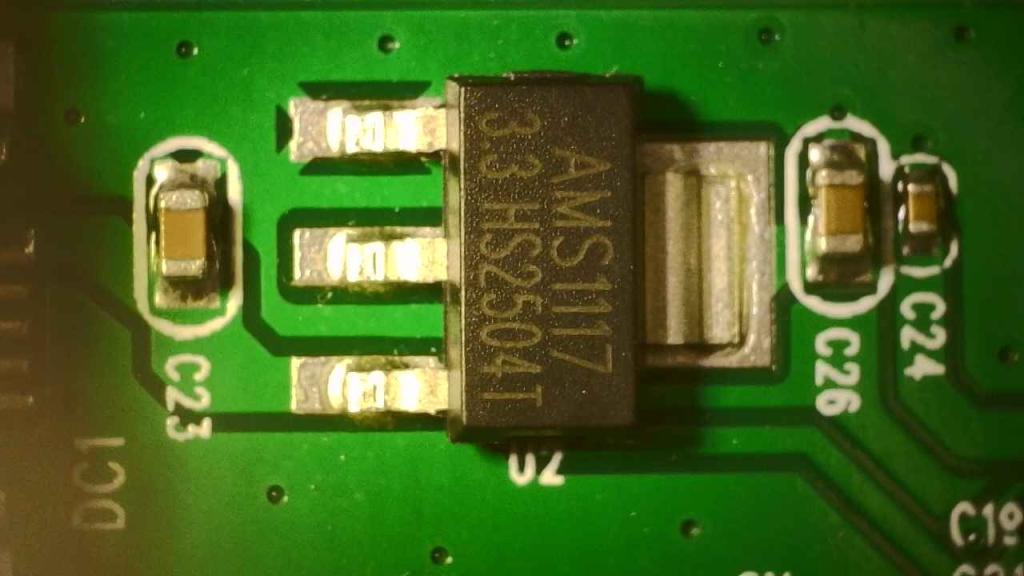 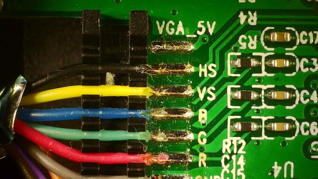 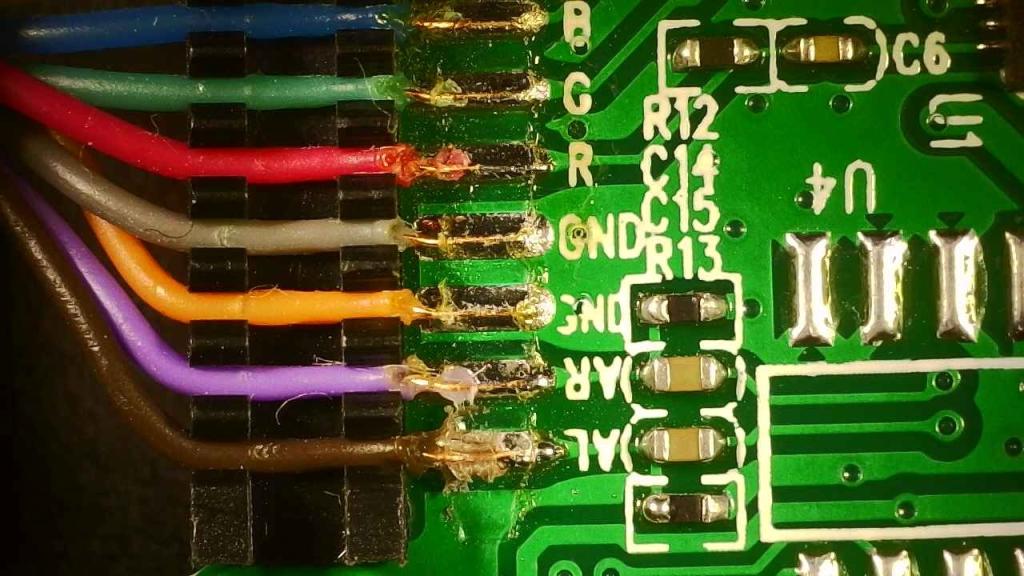 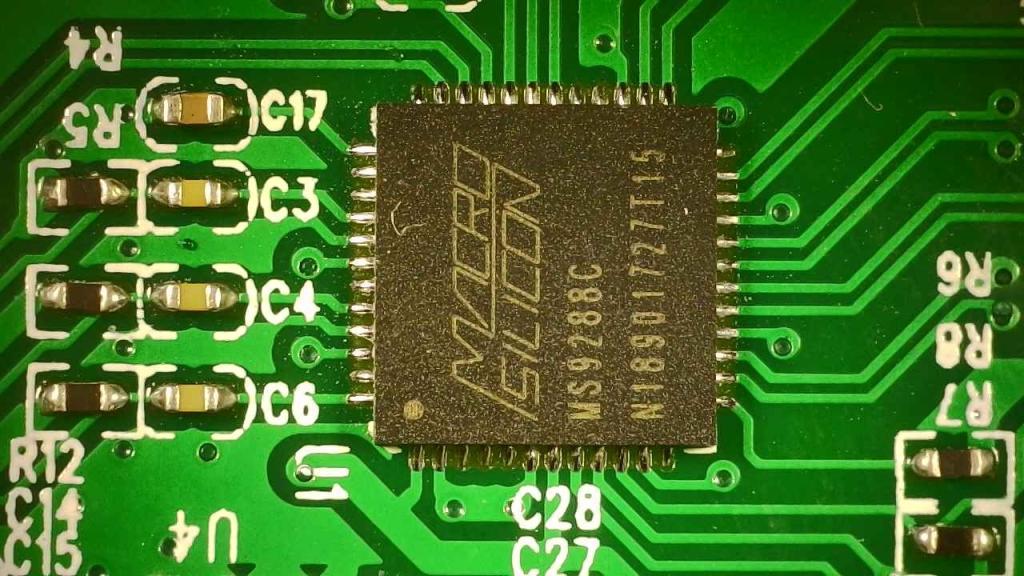 Best wishes! Joachim |
||||
| v.lenzer Senior Member Joined: 04/05/2024 Location: GermanyPosts: 131 |
"Does your board supply 5V to pin 9 of the VGA connector?" No, there is no connection. Neither from VBUS nor from VSYS. It is this board here from the forum: 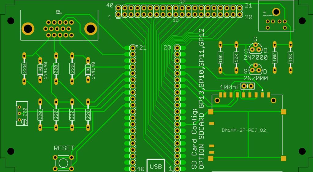 Best wishes! Joachim |
||||
| Mixtel90 Guru Joined: 05/10/2019 Location: United KingdomPosts: 8996 |
In my experience the VGA from the Pico is pretty bombproof. If you aren't getting something from that (with the correct firmware and configuration of course) then I suspect another problem. Mick Zilog Inside! nascom.info for Nascom & Gemini Preliminary MMBasic docs & my PCB designs |
||||
| v.lenzer Senior Member Joined: 04/05/2024 Location: GermanyPosts: 131 |
I can confirm that! I’m going to check the connections between the converter and the VGA connector now. Maybe a connection the converter needs is missing. I think it’s also time I familiarized myself with the basics of VGA technology; right now, I’m just fumbling around in the dark. Best wishes! Joachim |
||||
| Mixtel90 Guru Joined: 05/10/2019 Location: United KingdomPosts: 8996 |
VGA (at our level) is fine. Three analogue voltages and two digital pulses at around audio frequencies. Providing the sync lines are connected and are the right way round you'll get something, even if it's just a blank raster. DVI/HDMI on the other hand is the work of high speed demons. :) Four very high speed digital signals in parallel. Mick Zilog Inside! nascom.info for Nascom & Gemini Preliminary MMBasic docs & my PCB designs |
||||
| v.lenzer Senior Member Joined: 04/05/2024 Location: GermanyPosts: 131 |
First things first: it works perfectly. I connected the converter to my PC monitor, and it worked immediately. I identified the connections between the VGA port on the Picomite and the converter board. The pins on the VGA port—1 (RED), 2 (GREEN), 3 (BLUE), 6–8 (GND), 13 (HS), and 14 (VS)—match up correctly. According to the schematic, pin 5 on the VGA port is connected to GND; however, there is no connection on the board itself, nor is there a connection to the converter. Pin 10 on the VGA port is connected to the output of the trimmer (200 ohms) but not to the converter. I don't know if any of this matters. The monitor I tested it with first handles the HDMI signal from a Raspberry Pi without issues, so it is functioning correctly in that regard. I also noticed something else: when the converter is connected to the PC monitor and operating, it gets relatively hot. When connected to the monitor where it doesn't work, it stays cold. Could it be that the converter doesn't realize a monitor is connected? Edited 2026-06-13 22:58 by v.lenzer Best wishes! Joachim |
||||
| phil99 Guru Joined: 11/02/2018 Location: AustraliaPosts: 3331 |
They are just ground connections, connected to pin 23 of the Pico, between the sync and colour pins. See the schematic from Geoff's site. The trimmer adjusts the green so that you see pure white with CLS RGB(white). It makes little difference. The later version uses just 4 resistors, see Video Output in the manual. 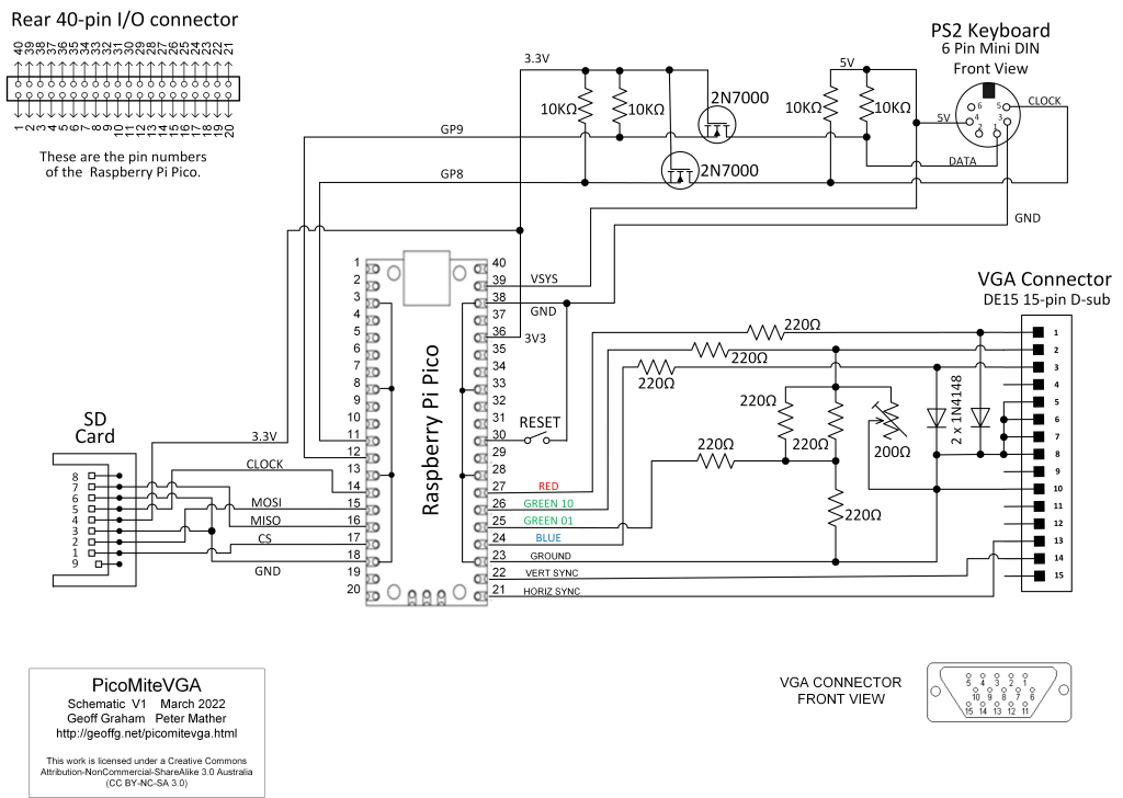 |
||||
| v.lenzer Senior Member Joined: 04/05/2024 Location: GermanyPosts: 131 |
Thank's for the explanations! Best wishes! Joachim |
||||
| Volhout Guru Joined: 05/03/2018 Location: NetherlandsPosts: 6007 |
Joachim, Picomite VGA supports only one VGA resolution. 640*480@60Hz (or 75 Hz). You can check when OPTION LIST When it shows 252000 It is 60Hz When it shows 315000 It is 75 Hz. 60Hz is common, and mandatory in the HDMI standard. 75Hz is less common, and may not be supported by your converter. Volhout P.S. Make sure that when you test with th PC, you set the screen to 640*480. Otherwise the test proves nothing. Edited 2026-06-14 16:46 by Volhout PicomiteVGA PETSCII ROBOTS |
||||
| phil99 Guru Joined: 11/02/2018 Location: AustraliaPosts: 3331 |
All of them work on my RP2350A VGA and very old monitor. Edited 2026-06-14 18:51 by phil99 |
||||
| Volhout Guru Joined: 05/03/2018 Location: NetherlandsPosts: 6007 |
Just checked PicoMiteVGA RP2040 version V60300 rc19 defaults to VGA at 75Hz (fresh OOTB). To set to 60Hz, type OPTION RESOLUTION 640,252000 Volhout P.S. actually Peter: this should be default 60Hz, since it is mandatory in most standards (like HDMI). Edited 2026-06-14 18:58 by Volhout PicomiteVGA PETSCII ROBOTS |
||||
| Frank N. Furter Guru Joined: 28/05/2012 Location: GermanyPosts: 1146 |
In the Picomite schematic, only one pin is connected to GND (Pin 10). Your adapter has two GND wires - Is it possible that there's simply a missing GND connection? Why don't you plug in your adapter and check the GND connections? Maybe there's just a missing GND connection? I once had a problem like that with a VGA monitor and the CMM2. Frank |
||||
| Mixtel90 Guru Joined: 05/10/2019 Location: United KingdomPosts: 8996 |
Mine shows 5,6,7 & 8 also connected to GND as well as 10. Mick Zilog Inside! nascom.info for Nascom & Gemini Preliminary MMBasic docs & my PCB designs |
||||
| phil99 Guru Joined: 11/02/2018 Location: AustraliaPosts: 3331 |
As does the circuit above, Posted: 11:50pm 13 Jun 2026 The two Gnd. wires in the adapter cable most likely go to the Sync. ⏚ (10) and one of the colour ⏚ (6, 7, 8). Long VGA leads often have 75Ω coax for the colour wires and a ⏚ pin for each shield. Easy to test with a meter from the converter to the plug. |
||||
| v.lenzer Senior Member Joined: 04/05/2024 Location: GermanyPosts: 131 |
Hello Frank! The two GND lines (the gray and orange cables in the picture) are connected to VGA socket pins 6, 7, and 8, as well as to both connector housings—and consequently to pins 10 and 5. I should mention, though: I thought pin 5 wasn't connected. That turns out to be incorrect. I got the pin numbering wrong because I didn't take into account that the socket is angled. That means the top row on the layout is actually the bottom one :( Best wishes! Joachim |
||||
| Page 1 of 2 |
|||||
| The Back Shed's forum code is written, and hosted, in Australia. | © JAQ Software 2026 |
