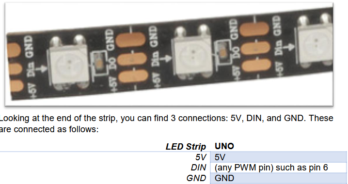
|
Forum Index : Microcontroller and PC projects : WS2812 LED Strip Pin Out
| Author | Message | ||||
| Nimue Guru Joined: 06/08/2020 Location: United KingdomPosts: 447 |
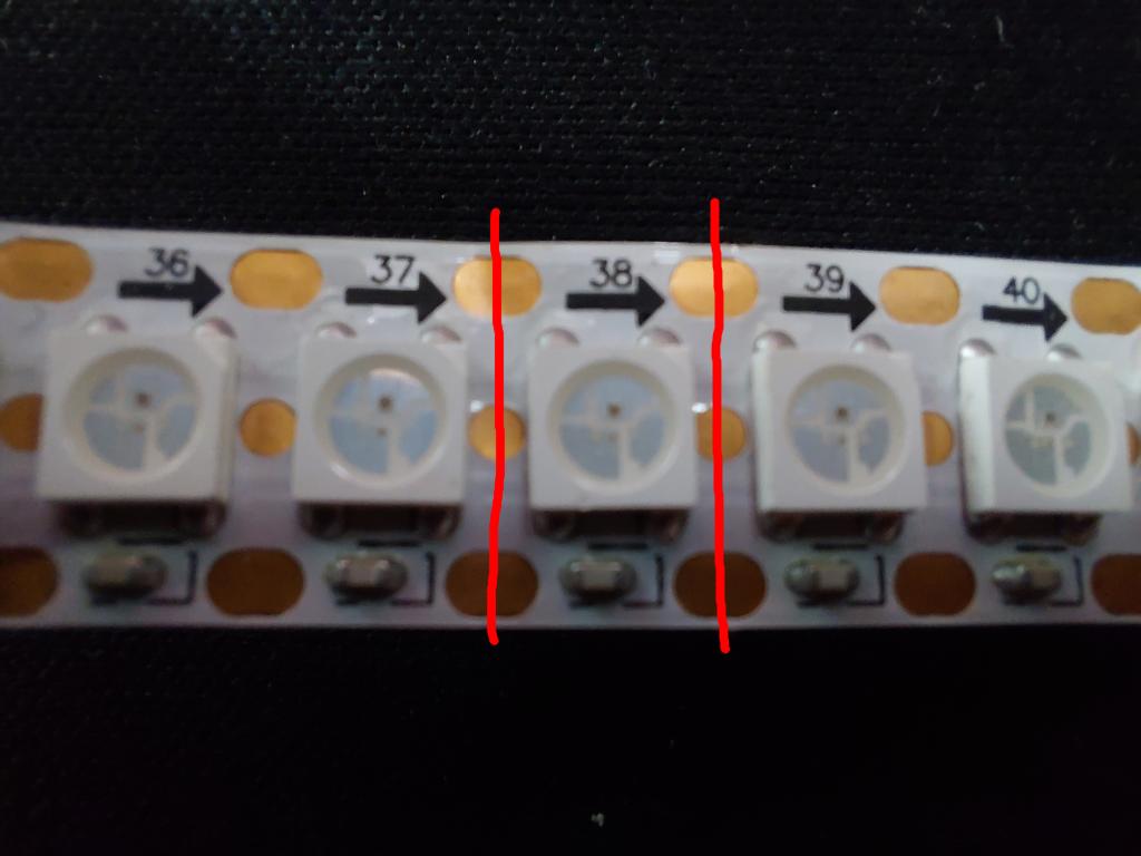
I want to separate out a 144LED/m strip into some separate LEDs. ![]() From the image say I want to separate off LED 38. So I cut as indicated and add wires to rejoin it - all OK. I'm a little lost over the 5V and Ground -- am assuming that DIN/DOUT is the centre pin. From what I find online I think GND is the pin nearest the 38 following the arrows 5V is the side with the resistor. Secondary question: the order of LEDS doesnt matter right? As long as they are connected in parallel and in one "line". The numbers on the strip are just for identification? Cheers G Entropy is not what it used to be |
||||
TassyJim![]() Guru Joined: 07/08/2011 Location: AustraliaPosts: 6575 |
My guess (based on similar strips) Top is 0V middle is Data I/O bottom is 5V Each LED is the same. The numbers are just to make it easier to count. Some strips run on 3.3V data others require the full 5V ![]() If your strip has leads, you could apply power to the most logical colours and measure on the strip. Alternatively, test the pins for continuity. The data pins should stand out. Jim Edited 2026-08-19 07:26 by TassyJim VK7JH MMedit |
||||
Bill.b![]() Senior Member Joined: 25/06/2011 Location: AustraliaPosts: 246 |
I use 5v strip and they work OK with 3.3v control signal i.e. from a picomite. Bill In the interests of the environment, this post has been constructed entirely from recycled electrons. |
||||
| JanVolk Guru Joined: 28/01/2023 Location: NetherlandsPosts: 405 |
Nimue, Unfortunately, I don't have enough information about this strip, and there are many varieties in circulation. Is there any further information on the back, the ends, or perhaps where you bought it? If we are talking about the WS2812 (5V) here, it might work with the existing firmware, but if you have a different type, I can't say for sure. There is also the WS2812B for 3.3V. I saw a similar image on AliExpress showing a 7.2mm 3535 DC5V 144 LEDs/m strip. On that strip, the arrow indicates GND, the capacitor's position marks the positive terminal, the middle-left pin is DI, and the right pin is DO—but I don't know if that is the specific type you have or if it works with the firmware. On other types, the labels GND, DI, DO, and 5V are clearly marked on the strip. Also, be careful with the pins on the PicoMite. Not all pins are 5V-tolerant—especially on the RP2040—though that applies to inputs; inserting a diode on the output might be a solution, though I’m not sure if that would work. Jan. Edited 2026-08-19 08:11 by JanVolk |
||||
| Mixtel90 Guru Joined: 05/10/2019 Location: United KingdomPosts: 9051 |
One way to deal with these strips is to power them from 5V via a big juicy diode. It drops the voltage to the strip a touch but brings the input voltage within the output voltage of a 3V3 Pico. That's if you're fussy, I'm not. Alternatively, a 1K resistor to drive the first LED will give the Pico some protection and doesn't seem to upset things. Mick Zilog Inside! nascom.info for Nascom & Gemini Preliminary MMBasic docs & my PCB designs |
||||
| The Back Shed's forum code is written, and hosted, in Australia. | © JAQ Software 2026 |