
|
|
Forum Index : Microcontroller and PC projects : Maximite Power Plotter
| Author | Message | ||||
| Gizmo Admin Group Joined: 05/06/2004 Location: AustraliaPosts: 5012 |
Hi Guys I'm starting a new thread to talk about a Maximite project I'll be working on. Actually I have a few Maximite projects on the go, but this thread will be about the power plotter. As I mentioned in the Maximite thread, I'm putting together a alternator power to RPM plotter. The idea is I use the Maximite to quickly plot a power/rpm curve on the screen, and save the figures in a excel file on the SD card. I've spent the last week playing around with the Maximite code and a interface to find a combination that give good figures on the screen. At first I was using an old servo motor and battery as the test subject, but it was a bugger of a thing to test with, the electric drill struggled to load it up correctly and give a nice range of RPM's. 
So I ditched that and put together a smaller test setup consisting of a stepper motor with crank handle, a couple of bridge rectifiers and resistors as the load/shunt. The stepper motor generates 2 phase AC, a few volts, enough for testing. 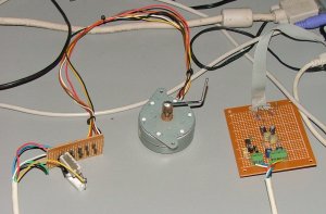
One of the problems I was having was erratic plots, the watts readings were very scattered. The software averages the figures for the RPM readings, so after cranking the stepper up and down a few times the plot would smooth out, but I wanted to see why it was so erratic in the first place. Me trusty old cro showed the problem. Bottom trace is the RPM input to the Maximite, I'm using the same clipping circuit I used on the PicLog, and as you can see it gives a nice clean stream of pulses. The top trace is the DC fed into one of the Maximites analogue inputs. Centerline is 0 volts, 1volt per division. A lot of AC hum. The Maximite is very fast at reading its analogue inputs, so it sees a voltage jumping up and down, explaining the erratic plot. 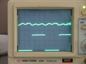
I did try some software averaging to smooth out the readings, but found a couple of 10uF caps across the inputs made all the difference. I do wish I could sync my camera with the cro. Trying to get a shot without the retrace is difficult. 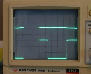
The program now reads the data in and plots a power curve on the screen. I'm using the Maximites period input to work out RPM, the frequency input only updates every second so thats a bit slow for this job. One little problem is the period input reads to milliseconds, meaning for a alternator with lots of magnets like a F&P, the RPM resolution spreads out noticably at higher RPM. For example, a 5ms period works out to 461rpm, a 6ms period is a big jump to 384rpm. Once we get into the lower RPM,s, the readings are much closer, ie 10ms = 230rpm, 11ms = 209rpm. For lower magnet count alternators its not a problem. I'll use some maths to fill in the RPM gaps anyway. So thats where its at. With the little problems sorted, next its on to making it all look pretty on the screen and give some meaningfull data. Glenn The best time to plant a tree was twenty years ago, the second best time is right now. JAQ |
||||
mac46 Guru Joined: 07/02/2008 Location: United StatesPosts: 412 |
Gizmo, I've been following along with you'r new project with interest. Will this be hard wired from the mill? Great work, and has huge potiential applications. .....Mac46 I'm just a farmer |
||||
| Gizmo Admin Group Joined: 05/06/2004 Location: AustraliaPosts: 5012 |
Hi Mac No, this will be more of a test instrument. You would use it to test the performance of a alternator, see what effect modifications have, and comparing alternators against eachother. It could also be used to test a alternator up on a windmill, so long as you can access the RPM, voltage and current, it will work, though the rpm range of the data will be limited to the wind conditions of that period of testing. Its easy to change the software running on the maximite. You could have several ( hundreds ) of programs stored on the SD card. One might be a windmill controller / logger, to keep the batteries charged, switch in dump loads etc. To change program, say to the power logger, you just type in Load "RW_PLOT" run and its now a RPM to Power logger, the program called RW_PLOT has been loaded and run. When your finished, load up the other program. Glenn The best time to plant a tree was twenty years ago, the second best time is right now. JAQ |
||||
| mac46 Guru Joined: 07/02/2008 Location: United StatesPosts: 412 |
Gizmo, I was never involved with programing, but do have a limited experiance with electronics. However this was years ago and so I'm pretty rusty on that subject. I can follow and understand part of what you'r doing. Still very interesting. .....Mac46 I'm just a farmer |
||||
sparkey Senior Member Joined: 15/06/2011 Location: AustraliaPosts: 819 |
dear gizzmo could you email me the program you used for this plotter as i would find it very easy to start to modify it for my project on my wind generator ..oh by the way mine is a three phase it came from jaycar origanally ...specks said it was 500 watt but ive seen it put out much more current oh also it is rated at 24 volts but capeable of about 40 volts dc after rectification it came with a controller but its crap built my own 3 phase rectifier out of two 50 amp bridge rect`s...regards sparkey... technicians do it with least resistance |
||||
