
|
|
Forum Index : Microcontroller and PC projects : LCD schematic - pls explain open collecto
| Author | Message | ||||
| Ray B Senior Member Joined: 16/02/2007 Location: AustraliaPosts: 219 |
The following articles will explain all about LCD displays http://www.epemag.wimborne.co.uk/lcd1.pdf http://www.epemag.wimborne.co.uk/lcd2.pdf Following is my rewrite of Geoff's LCD code to provide more comments and examples of sending variables in other lines of test to the LCD and also some of my idiotic diagnostic strinds to print on my PC so I can see what the MM is doing when. Code follows: 10: ' Filename "RayLCD_4.bas" 15: ' this explains a lot of the LCD commands 20: GOSUB 11000 ' Initialise the LCD ' ' LCD is now setup to receive characters and display them ' 25: FOR n = 1 TO 100 30: LCD_line1$ = " Hello World " 35: LCD_line2$ = " Maximite LCD " 40: GOSUB 12000 ' to routine to send text characters to LCD ' ' we have now sent a couple of lines to LCD ' now print out some diagnostic text & sent 2 diff rows of text inc a variable TIME$ ' 45: PRINT , "loop number", n , LCD_line1$, LCD_line2$ 'for diagnostic purposes 50: PAUSE 1000 'for diagnostic purposes 55: lCD_line1$ = "time = "+TIME$ ; 'load new string & add TIME$ 60: LCD_line2$ = "qwerty " 'just some more text for diagnostic purposes 65: GOSUB 12000 ' to routine to send text characters to LCD 70: PRINT , "loop number", n ,LCD_line1$, LCD_line2$ 75: PAUSE 1000 80: NEXT n 85: END 90: ' 95: ' 10000: '''''''''''''''''''''''''''''''''''''''''''''''''''''''''''' '''' 10010: ' LCD driver for standard 16 x 2 LCDs 10020: ' Geoff Graham, March 2011 10030: ' 10040: ' For example: futurlec.com LCD16X2 10050: ' altronics.com.au Z7001 10060: ' jaycar.com.au QP5512 10070: ' 10080: ' To use: 10090: ' - execute GOSUB 11000 to initialise display 10100: ' - then load the text strings into the 10110: ' variablesLCD_line1$ and LCD_line2$ 10120: ' - execute GOSUB 12000 to display the text 10130: ' 10140: ' See the file lcd.pdf for the schematic. 10150: ' Maximite pin 11 is LCD line RS (4) which is 'Register Select' a L = means data lines will be COMMANDS & H = means data lines = characters 10155: ' Maximite pin 12 is LCD line EN (6) which is 'Enable' data is transferred to LCD on a H to L transition 10157: ' LCD R/W line is always L to vreceive commands & characters 10160: ' Maximite pins 13 to 16 are D7 to D4. R/W is grounded 10180: '''''''''''''''''''''''''''''''''''''''''''''''''''''''''''' '''' 10190: ' 10200: ' 11000: '''''''''''''''''''''''''''''''''''''''''''''''''''''''''''' '''' 11010: ' Initialise the LCD 11020: ' 11030: FOR i = 11 TO 16 : SETPIN i, 9 : NEXT i ' set all pins to open collector output and 5 volt 11040: _LCD_byte = &B0011 : GOSUB 13090 : PAUSE 5 ' reset - part of a 3 byte sequence of 0011xxxx to properly reset LCD 11050: _LCD_byte = &B0011 : GOSUB 13090 : PAUSE 5 ' reset 11060: _LCD_byte = &B0011 : GOSUB 13090 : PAUSE 5 ' reset 11070: _LCD_byte = &B0010 : GOSUB 13090 : PAUSE 2 ' 4 bit mode 11080: _LCD_byte = &B00101100 : GOSUB 13000 ' See Function Set in table where = 4 bit, 2 lines,5x10 dot chr format 11090: _LCD_byte = &B00001100 : GOSUB 13000 ' display on, no cursor underline, blink off 11100: _LCD_byte = &B00000110 : GOSUB 13000 ' increment on write, display shift off 11110: _LCD_byte = &B00000001 : GOSUB 13000 ' $01 = clear display 11120: RETURN 11130: ' 11140: ' 12000: ' '''''''''''''''''''''''''''''''''''''''''''''''''''''''''''' '''' 12010: ' send the two lines to the LCD 12020: ' the text is in LCD_Line1$ and LCD_Line2$ 12030: ' 12040: _LCD_byte = &H80 : GOSUB 13000 ' select the 1st line 12050: FOR _LCD = 1 TO 16 12060: _LCD_byte = ASC(MID$(LCD_Line1$, _LCD, 1)) 12065: PRINT "sending ...",MID$(LCD_Line1$, _LCD, 1),"which equals ",_LCD_byte ' this line for diagnostic purposes 12066: PAUSE 50 ' time to view line above 12070: PIN(11) = 1 : GOSUB 13000 ' send the character - sending one character at a time 12080: NEXT _LCD 12085 ' 12090: _LCD_byte = &B11000000 : GOSUB 13000 ' select the 2nd line 12100: FOR _LCD = 1 TO 16 12110: _LCD_byte = ASC(MID$(LCD_Line2$, _LCD, 1)) 12120: PIN(11) = 1 : GOSUB 13000 ' send the character 12130: NEXT _LCD 12140: RETURN 12150: ' 12160: ' 13000: '''''''''''''''''''''''''''''''''''''''''''''''''''''''''''' '''' 13010: ' Send a byte to the LCD 13020: ' the data to be sent is in _LCD_byte 13030: ' 13040: PIN(13) = _LCD_byte AND &B00010000 ' output the 1st 4 bits - this isc LCD D7 13050: PIN(14) = _LCD_byte AND &B00100000 ' output the 1st 4 bits - this isc LCD D6 13060: PIN(15) = _LCD_byte AND &B01000000 ' output the 1st 4 bits - this isc LCD D5 13070: PIN(16) = _LCD_byte AND &B10000000 ' output the 1st 4 bits - this isc LCD D4 13080: PIN(12) = 1 : PIN(12) = 0 ' tell lcd to accept data by driving EN (Enable line) H to L 13090: ' Entry point to send just 4 bits to the LCD 13100: PIN(13) = _LCD_byte AND &B00000001 ' output the 2nd 4 bits 13110: PIN(14) = _LCD_byte AND &B00000010 13120: PIN(15) = _LCD_byte AND &B00000100 13130: PIN(16) = _LCD_byte AND &B00001000 13140: PIN(12) = 1 : PIN(12) = 0 : PIN(11) = 0 ' tell lcd to accept data by driving EN (Enable line) H to L 13150: RETURN RayB from Perth WA |
||||
James_From_Canb Senior Member Joined: 19/06/2011 Location: AustraliaPosts: 265 |
I've modified the original code to use a 4 x 20 LCD screen. I found the start addresses for the lines by trial-and-error, because I couldn't find them in the specifications. Please let me know if it doesn't work on your 20 x 4. Let's see if the file upload works.... James 2011-07-03_232346_LCD_4x20.zip My mind is aglow with whirling, transient nodes of thought careening through a cosmic vapor of invention. Hedley Lamarr, Blazing Saddles (1974) |
||||
stuarts Senior Member Joined: 15/06/2011 Location: AustraliaPosts: 199 |
James, the hitachi 44780 chipset used in these displays typically have 80 bytes of RAM. Just enough to display 4 x 20. Usually you will find the lines start at 0,20,40 and 60 decimal. I do have one 4 x 40 display. It has 2 44780s which means you have to initialise 2 displays and whether you want to work in the top half of the display or the bottom detirmines which chip select you activate to use the display. Stuart Time is nature's way of keeping everything from happening all at once. |
||||
| James_From_Canb Senior Member Joined: 19/06/2011 Location: AustraliaPosts: 265 |
Thanks Stuart, Yes, I read that on various sites, but it didn�t work for me if I substituted it into Geoff�s code. I only got the first character printing on the second line, for instance. First line OK, third line OK, nothing at all on the 4th line. For instance, Geoff uses &B1100 0000 to select the second line. The highest bit (D7) means SET DD RAM Address. The next 7 bits are AC6 down to AC0. So Geoff used 0100 0000 (=64 decimal) to set the second line for the 2 line LCD. Not an even multiple of 20. So I wrote a little program that used 0 to 127 as start addresses and wrote an X to the screen. The addresses I used in the code are those that allowed a full line of Xs to be written. BTW, if I set the address to line 1 and write 80 contiguous characters, they fill out each line correctly. Maybe I did a bad job soldering and shorted out an address line - or maybe it's something weird about my eBay 20x4 LCD panel with blue backlight, which cost under $10 including shipping from China. Whatever, I put all the constants at the top of the program. If anyone has an LCD panel that works with 0, 20, 40 and 60, just change the values. I'm looking forward to trying one of those 4x 40 displays. Now if I can just find one for under $10 from eBay.... 
James My mind is aglow with whirling, transient nodes of thought careening through a cosmic vapor of invention. Hedley Lamarr, Blazing Saddles (1974) |
||||
| Ray B Senior Member Joined: 16/02/2007 Location: AustraliaPosts: 219 |
Well done James this publishing of code for others to learn from is what forums are all about and what Bob Devries touched on in an earlier post with him writing an extended MM Basic manual. What ever happened about the idea of somewhere code could be dumped for others to use? Must now go on ebay and try and find your 20.4 LCDs.... RayB from Perth WA |
||||
| Talbit Senior Member Joined: 07/06/2011 Location: AustraliaPosts: 210 |
Stuart, See my post yesterday re the mistake in Geoff's LCD circuit. In your above code, you have changed the remark re the pins at line 10160 but your code is the same. No doubt you've actually run it with your above code. I recon with Geoff's original code AND original circuit, it won't work. I believe the pins should be 13 to 16 are D4 to D7 and Geoff's code unchanged. How have you wired up your 20 X 2 display? Regards Talbit Talbit |
||||
| rhamer Senior Member Joined: 06/06/2011 Location: AustraliaPosts: 174 |
I've got a pile of them, I'll send you one with your order. Regards Rohan Rohan Hamer HAMFIELD Software & Hardware Solutions Makers of the Maximite Expander. http://www.hamfield.com.au |
||||
| stuarts Senior Member Joined: 15/06/2011 Location: AustraliaPosts: 199 |
Talbit, I haven't used any lcd on the maximite yet. I was using the 4x40 a lifetime ago on a microcontroller called the Tiny Tiger. They were quite advanced for their time. It was just a comment on the HD44780 controller and how it maps the display and therefore the limit that they have with displays with more than 80 characters. Stuart Time is nature's way of keeping everything from happening all at once. |
||||
| James_From_Canb Senior Member Joined: 19/06/2011 Location: AustraliaPosts: 265 |
I'm back from work - the curse of the Maximite enthusiast. During lunch I found this link LCD Link. It says something similar to Stuart, and I had read on other sites - that the lines start at 00H, 40H, 20H and 60H. The control byte start with a leading 1 (80H or 128), followed by the address. So I would expect the control byte to be line 1: 80H + 00H = 80H = 128 line 2: 80H + 40H = C0H = 192 line 3: 80H + 20H = A0H = 160 line 4: 80H + 60H = E0H = 224 but the same site says, under useful commands: Moves cursor to first address on the left of LINE 1 = 80H = 80H + 00H. Tick Moves cursor to first address on the left of LINE 2 = C0H = 80H + 40H. Tick Moves cursor to first address on the left of LINE 3 = 94H = 80H + 14H (20D). ??? Moves cursor to first address on the left of LINE 4 = D4H = 80H + 54H (84D). ??? The author has come up with the same numbers I found for lines 3 and 4, but I have no idea why they work. Anyway, at least it's unlikely I have a solder bridge or similar, so I'm reasonably confident the code is correct. I just don't know why, because lines 3 and 4 are supposed to start from addresses 20H and 60H. Next on the list: Scrolling text, an LCD_LOCATE function and more constants to define LCD operations. My mind is aglow with whirling, transient nodes of thought careening through a cosmic vapor of invention. Hedley Lamarr, Blazing Saddles (1974) |
||||
| Ray B Senior Member Joined: 16/02/2007 Location: AustraliaPosts: 219 |
For another great LCD Interfacing reference don't overlook the PicAxe Manual # 3 pages 31-42 available from http://www.rev-ed.co.uk/docs/picaxe_manual3.pdf. Speaking of PicAxe don't overlook the new M2 range of controllers with expanded specs http://www.rev-ed.co.uk/docs/picaxem2.pdf The hubble 08 now has 2K memory, supports 1800 lines of code with I2C and all of the other hi level instructions for A$5. When we get serial onto MaxiMite we can progress to MaxiMite driving a PicAxe network either through cable or wireless but that is all 6 months away. RayB from Perth WA |
||||
| Ray B Senior Member Joined: 16/02/2007 Location: AustraliaPosts: 219 |
LCD Rows/ Columns this should explain 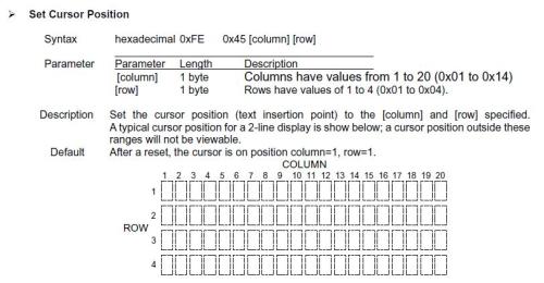
RayB from Perth WA |
||||
| The Back Shed's forum code is written, and hosted, in Australia. | © JAQ Software 2025 |
