
|
|
Forum Index : Microcontroller and PC projects : Another I2C implementation
| Author | Message | ||||
| seco61 Senior Member Joined: 15/06/2011 Location: AustraliaPosts: 205 |
Hi All. Here is another I2C implementation that is available for testing: Download here And a program that sends data to a TftA I2C display (a project that I helped develop!): TftA.bas And the same program but using the interrupt: TftA_Interrupt.bas The implementation fully supports bus arbitration (ie bus collisions in a multi master environment) The implementation has 4 commands: i2cen i2cdis i2csend i2crcv i2cen initialises the i2c module and disables the setpin and pin commands/functions for pins 12 and 13 i2cen speed, timeout [, int_line] where speed is either 100 (for 100K) or 400 (for 400K) timeout is a value in milliseconds after which the send and receive commands will be interrupted if they have not completed a value of zero for timeout will disable the timeout int_line is an optional argument that supplies the line number of an interrupt routine to be run when the send or receive command completes if this is not supplied, the send and receive command will return when they have completed (or timed out) if it is supplied then the send and receive will complete immediately and the command will execute in the background i2cdis disables the i2c module and reenables the standard pin 12 and 13 functionality (and will send a stop if the bus is still held) i2cdis i2csend sends data to the slave device i2csend addr, bus_hold, sendlen, senddata [,sendata ....] where addr is the slave i2c address bus_hold if set (ie not zero) will keep control of the bus after the command (a stop condition will not be sent at the command completion) sendlen is the number of bytes to send senddata is the data to be sent - this can be specified in various ways: i2csend &h6f,1,3,&h23,&h43,&h25 the data can be supplied on the command as individual bytes i2csend &h6f,1,3,array(0) the data can be in a one dimensional array (the subscript does not have to be zero and will be honoured) bounds checking is performed i2csend &h6f,1,3,string$ the data can be string variable (not a constant) i2crcv receives data from the slave device, and optionally will send a command first i2crcv addr, bus_hold, rcvlen, rcvbuf [,sendlen, senddata [,sendata ....]] where addr is the slave i2c address bus_hold if set (ie not zero) will keep control of the bus after the command (a stop condition will not be sent at the command completion) rcvlen is the number of bytes to receive rcvdata is the variable to receive the data - this is a one dimensional array or if rcvlen is 1 then this may be a normal variable the array subscript does not have to be zero and will be honoured - bounds checking is performed sendlen is the number of bytes to send first - this is optional senddata is the data to be sent - this can be specified the same as in i2csend i2crcv &h6f,1,1,avar i2crcv &h6f,1,5,anarray(0) i2crcv &h6f,1,4,anarray(2),3,&h12,&h34,&h89 i2crcv &h6f,1,3,anarray(0),4,anotherarray(0) After the completion of a send or receive command the auto variable MM.I2C will contain one of: 0 - all completed OK 1 - we received a NACK response 2 - command timed out Have fun!! Regards Gerard (vk3cg/vk3grs) |
||||
| aargee Senior Member Joined: 21/08/2008 Location: AustraliaPosts: 255 |
This is rather neat how lots of people are starting to modify and play with the firmware, but I fear that we may shoot ourselves in the foot. If we have too many firmware variants, with different commands, the Maximite itself may end up suffering in that no-one will know which variant of the firmware they need to do which job, without a lot of fiddling about. This might be a big put-off for new users, especially those without a lot of this sort of knowledge. I suggest that Geoff should be the one to say which code becomes standard, whether he writes it or not. Or maybe the provision of some sort of function library where the core code stays the same but if you want to run the "BlahBlah coms routines" you just add the library, though this is almost as much effort as loading whatever variant someone has created like it is now. Having said that, congrats to Seco61 and KSDesigns for your I2C work. - Rob. For crying out loud, all I wanted to do was flash this blasted LED. |
||||
jman Guru Joined: 12/06/2011 Location: New ZealandPosts: 711 |
Silly question "pins 12 and 13" Are these the PIC pin numbers or the connector pin numbers Thanks John EDIT Got it just needed to look at PIC datasheet |
||||
| seco61 Senior Member Joined: 15/06/2011 Location: AustraliaPosts: 205 |
Hi John. These are the "logical" pin numbers that Geoff uses in MMBasic for the Pin and SetPin commands/functions. The logical pin 12 maps to MCU pin 43 (SDA1) and pin 6 on the I/O connector (revised schematic) or pin 21 (original schematic). The logical pin 13 maps to MCU pin 44 (SCL1) and pin 8 on the I/O connector (revised schematic) or pin 19 (original schematic). Pullup resistors are required on both these lines - I used 2.2K connected to the 5V line (I/O connector pin 23 (revised schematic) or pin 4 (original schematic)). A ground will also have to be run to the I2C device (I/O connector pins 1,2,25,26). regards Gerard Regards Gerard (vk3cg/vk3grs) |
||||
| jman Guru Joined: 12/06/2011 Location: New ZealandPosts: 711 |
Hi Gerard Thanks for the info It now works :) 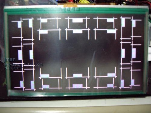
I have attached a pic of the screen running I assume this the intended pattern ? Regards John |
||||
| seco61 Senior Member Joined: 15/06/2011 Location: AustraliaPosts: 205 |
Hmm... The screen is not what I would quite expect - have you loaded your fonts into the TftA? 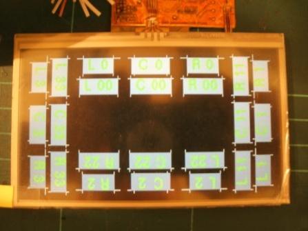
regards Gerard Regards Gerard (vk3cg/vk3grs) |
||||
| jman Guru Joined: 12/06/2011 Location: New ZealandPosts: 711 |
Nope Missed that one :) I have to ask you for your assistance to load the fonts Regards John |
||||
| seco61 Senior Member Joined: 15/06/2011 Location: AustraliaPosts: 205 |
Hi John. If you have a TrxAVR connected to the TftA then the fonts can be uploaded to the TftA using Hobcat. If not then you could connect a serial interface to the TftA and then use the SPP Terminal program (available on the TftA_Central group). Failing all that, then I could write a MMBasic program that will do the upload of the fonts. The font file would have to be copied to the SD Card first. Regards Gerard Regards Gerard (vk3cg/vk3grs) |
||||
| jman Guru Joined: 12/06/2011 Location: New ZealandPosts: 711 |
Hi Gerard I dont have a TrxAVR :( "If not then you could connect a serial interface to the TftA and then use the SPP Terminal program (available on the TftA_Central group). " I will have a go at the Terminal method If I fail could i bother you for a MMbasic method Many Thanks for the help John |
||||
| seco61 Senior Member Joined: 15/06/2011 Location: AustraliaPosts: 205 |
Hi John. You will have to build a circuit to convert the TftA 3.3V serial lines to an appropriate level to interface to a serial port. I used a MAX3232E for my level conversion, but others have used a simple 2 transistor method (I believe the details are on TftA_Central). I have had a quick look at the MMBasic file handling capabilities, and to do "binary" input and output I will have to create a couple of new custom commands for MMBasic. This should not be too difficult and I can see a use for it for other purposes. I will put it on the (somewhat lengthy) to do list. Regards Gerard Regards Gerard (vk3cg/vk3grs) |
||||
| jman Guru Joined: 12/06/2011 Location: New ZealandPosts: 711 |
Hi Gerard As you know it is now sorted now my pic looks like yours :) Thanks again for the help John 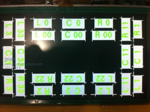
|
||||
| The Back Shed's forum code is written, and hosted, in Australia. | © JAQ Software 2026 |
