
|
|
Forum Index : Microcontroller and PC projects : RTC
| Author | Message | ||||
| ajkw Senior Member Joined: 29/06/2011 Location: AustraliaPosts: 290 |
I had an idea for implementing a Real Time Clock to my Maximite but have hit the wall. My idea is to use a DS1302 RTC and bit bash my way into and out of it with some code in the autorun.bat meaning the Maximite time is set whenever it boots. The Maximite would then keep the time itself and you could of course update the time from the RTC at anytime you choose. My problem is with writing and reading digital bits on a single I/O to/from the DS1302. With the open collector it seems you need a pull up resistor to write high but this becomes a problem when you want to read with the pull up keeping the pin high. The DS1302 only needs 3 lines, select, clock and data. I have considered using a 4th line to divert/switch the read to the Maximite to another pin but then that is 5 or half of your 5V digital lines. Seems to be too many. I have looked at the I2C but is it correct that it uses an address byte first, this would be a problem I feel with the extra data the DS1302 would know nothing of. I2c brings in the DS1307 but I already have the 1302's With this set up I planned to house the RTC circuit inside the Maximite case instead of on a outside add on board. There is enough room even with a CR2 back up battery. Anybody with any ideas? (The second paragraph is my problem. The rest is for your consideration and some background to my idea.) Anthony. |
||||
| Ray B Senior Member Joined: 16/02/2007 Location: AustraliaPosts: 219 |
Anthony understand where your coming from.... When your running off a USB port from a PC consider James post of 19th June re using macro in TeraTerm... great find... Post starts of with following: "I downloaded the latest version (V4.69) of TeraTerm from Sourceforge. It's powerful. The script below sets the title of the terminal window, connects to the MaxiMite and sets the date and time. The macro language can also process screen output from the Maximite which looks interesting." unquote But as I suspect your wanting a stand alone RTC for say a portable datalogger in that case like me you just wait until MM standardizes some of the I2C methods. As far as implimenting I2C attached is a tutorial from PICAXE which may of use to you although you seem to know what your doing - otherwire it is an excellent tutorials for I2C virgins. This gives examples in PICAXE BASIC which will not be too different to what becomes standard with MM I'm sure 2011-07-16_214806_axe110_i2c.pdf Enjoy.... RayB from Perth WA |
||||
stuarts Senior Member Joined: 15/06/2011 Location: AustraliaPosts: 194 |
Anthony, if you are going to try to bitbang i2c, the only real option is to use 2 pind for the data line. One set as open collector, and one as an input. Connect them together and then the device can pull the open collector pin to gnd, and you can read it on the other pin. The Maximite Basic doesn't let you read the value of an output pin. I am assuming that the chip you are using uses SPI. I suspect you will have the same problem with it as well. One of the things I like about i2c is that you only need 2 lines, clk and data. To get a basic i2c running using basic code needs 3, so its not too expensive on data pins as you can have multiple devices on the same bus. I currently have 2 DS1631 thermometers, and 2 8574 8 bit parallel i/o chips all hanging off the same 2 lines using the firmware with I2C code inbuilt. When my RTC arrives, it will be added as well. A little more code to get it running, but no more hardware resources on the Maximite. I've got i2c running bitbanged from basic and apart from being slow, it works fine. I dont see why you couldn't do the same with the SPI RTC as well. I'm waiting on an I2C RTC board to arrive from futurlec.com right now. At $7.90 I couldn't see the need to make one myself. I'm now running one of the i2c in firmware mods on one of my Maximites and my bitbanged code on the other. Its much nicer with inbuilt I2C commands. There is definitely no problem with having the pullup resistor to provide a 1 for output as you need the same pullup resistor for the RTC to provide a 1 as well. Stuart Time is nature's way of keeping everything from happening all at once. |
||||
| seco61 Senior Member Joined: 15/06/2011 Location: AustraliaPosts: 205 |
Hi All. After some emails with Geoff, I believe that the next beta version of MMBasic (v2.4b) will contain an I2C implementation. And the release should be out in the next week or two. regards Gerard Regards Gerard (vk3cg/vk3grs) |
||||
donmck Guru Joined: 09/06/2011 Location: AustraliaPosts: 1310 |
AHA! Then the initial march will be in the direction of I2C. Should prove interesting. And thanks Gerard. Cheers Don... https://www.32v8.com/1 |
||||
jman Guru Joined: 12/06/2011 Location: New ZealandPosts: 711 |
That is wonderfull news I get edit back and the prompt command John |
||||
| ajkw Senior Member Joined: 29/06/2011 Location: AustraliaPosts: 290 |
Hi, Thanks to those that replied. It all helped. I can report that after a rethink on how the RTC writes back (thanks to Stuarts There is definitely no problem with having the pullup resistor to provide a 1 for output as you need the same pullup resistor for the RTC to provide a 1 as well.) I have been able to interface the DS1302 with 4 I/O lines. Also, yes the DS1302 is using SPI. I have just seen some meaningful data back from the RTC. It may only be a binary string counting seconds but I'm talking to it. 
Now it's just some more coding to convert the binary to bytes and I think I will have a working RTC. I just hope I'm not counting my ticks before they clock (eggs and hatching) writing this now but it looks good. Regards, Anthony. |
||||
| stuarts Senior Member Joined: 15/06/2011 Location: AustraliaPosts: 194 |
Anthony, maybe what I should have said is that both the Maximite and the SPI device are open collector devices. Typically in I2C you will find a pullup at each end of the bus. Stuart Time is nature's way of keeping everything from happening all at once. |
||||
| ajkw Senior Member Joined: 29/06/2011 Location: AustraliaPosts: 290 |
Stuart, I worked it out that they are both open collector from what you wrote in your first post. I now leave he write pin of the Maximite high which allows the RTC to pull it low as required which I then read on a on 4th line/pin. Is talking away nicely. It seems I2C may well be ultimately easier but am enjoying this little challenge for now. Anthony. |
||||
| jman Guru Joined: 12/06/2011 Location: New ZealandPosts: 711 |
Hi I have managed to get a DS1307 working with Gerard's I2C code. Here is my attempt rough i know but it works Once you have the correct time set on the Maximite issue run 600 this will write the current date and time to the DS1307 Then just issue run and your Maximite will have the correct date and time no pc required :) Enjoy John 100 ' I2C RTC based On DS1307 Secs,Mins,Hours,Day,Date,Month,Year,Control 200 DIM RTCbuff(255) 220 i2caddr = &h68 ' DS1307 I2C address 250 i2cen 100,100 ' Enable I2C 260 i2crcv i2caddr, 0, 8, RTCbuff(0), 1, 0 265 i2cdis 270 BCDTEMP = RTCBuff(0) 280 Gosub 1000 290 sec$ = str$(decimal) 295 BCDTEMP = RTCBuff(1) 300 gosub 1000 305 min$ = str$(decimal) 310 BCDTEMP = RTCBuff(2) 315 gosub 1000 320 hours$ = str$(decimal) 325 BCDTEMP = RTCBuff(4) 330 gosub 1000 340 day$ = str$(decimal) 350 BCDTEMP = RTCBuff(5) 360 gosub 1000 370 month$ = str$(decimal) 380 bcdtemp = rtcbuff(6) 390 gosub 1000 400 year$ = str$(decimal + 2000 ) 440 t$ = hours$+":"+min$+":"+sec$ 442 D$ = day$+"/"+month$+"/"+year$ 445 time$ = T$ 446 date$ = D$ 450 ? "Time has been set to ";time$ 460 ?"Date has been set to ";date$ 500 end 600 ' Get time from time$ and date$ 610 tempdec = val(left$(time$, 2)) 615 gosub 1100 617 hours = hex 620 tempdec = val(mid$(time$, 4, 2)) 625 gosub 1100 627 minutes = hex 630 tempdec = val(right$(time$, 2)) 635 gosub 1100 637 seconds = hex 640 tempdec = val(left$(date$, 2)) 645 gosub 1100 647 day = hex 650 tempdec = val(mid$(date$, 4, 2)) 655 gosub 1100 657 month = hex 660 tempdec = (val(right$(date$, 4)) - 2000) 665 gosub 1100 667 year = hex 670 rtcctrl = &h10 680 rtcwday= &h1 690 ' Write Time to RTC 700 i2caddr = &h68 ' DS1307 I2C address 710 i2cen 100,100 ' Enable I2C 720 ' i2csend i2caddr, 1, 1 , 1 725 i2csend i2caddr, 0, 9, &h0, seconds, minutes, hours, rtcwday, day, month, year, rtcctrl 730 i2cdis 770 ? "0=ok 1=nack 2=timeout"; mm.i2c 775 ? "RTC has been set to ";time$;" ";date$ 780 end 1000 ' Convert to Decimal 1010 Decimal = fix(BCDTemp / 16) * 10 1020 Decimal = Decimal + (BCDTEMP AND &hF) 1030 Return 1100 ' Convert to Hex 1110 hex = fix(tempdec / 10) * 16 1120 hex = hex OR ((tempdec / 10) - (fix(tempdec / 10))) * 10 1140 return |
||||
| ajkw Senior Member Joined: 29/06/2011 Location: AustraliaPosts: 290 |
Hi, I am happy to report that I am greeted by the correct time when I turn on my Maximite. The code needs some tidy up after editing it on the fly but it WORKS!
If any one wants to try all you need is a DS1302, a crystal and the code. The parts are well priced from Dontronics (and friendly service too). The code I will tidy a little first. Anthony. |
||||
| ajkw Senior Member Joined: 29/06/2011 Location: AustraliaPosts: 290 |
Hi, I see in the new firmware update 2.4B that you can now read from a digital output pin. That will get me back to 3 pins which was the problem to which I originated this thread. I am sure the ic2 guys will be happy to have an official release also. The DS1302 has been working away nicely and I have the board nicely secured inside the maximite case. If any one would like to give the DS1302 a try and do some programming using an SPI interface I am happy to provide a copy of the code and further pictures. Attached is a picture at the conclusion of my autorun. My prompt is 2 lines, the time, the current directory and the actual prompt on the second line. 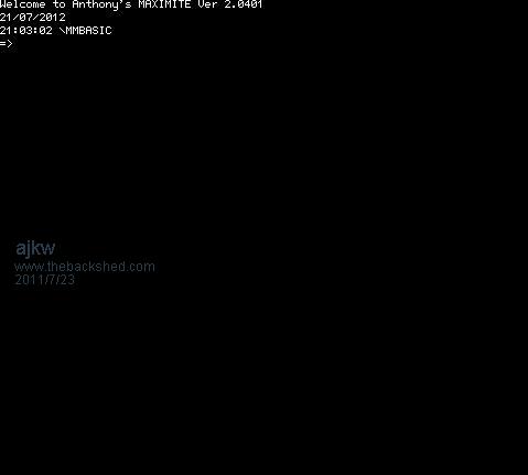
Cheers, Anthony. PS. The screen shot is a couple of days old. I should have done another one and uploaded it instead. |
||||
VK6MRG Guru Joined: 08/06/2011 Location: AustraliaPosts: 347 |
Looks good! nice work!  Its easier to ask forgiveness than to seek permission! ............VK6MRG.............VK3MGR............ |
||||
crackerjack Senior Member Joined: 11/07/2011 Location: AustraliaPosts: 164 |
Hi - I am reviving a way old thread here.... I have a DS1302 and a 32.768 xtal spare and wanted to have a go at implementing a RTC using these - particularly now as SPI is available in 2.5D I started doing this the hard way - bit-banging away, and then the announcment came last week from Geoff regarding SPI. I know that the DS1302 does not actually implement SPI, but rather a 3-wire interface (however, SPI can be used to communicate with the DS1302 - I believe). I wonder if ajkw (Anthony) would still be willing to share his original code such that it can be adapted to using the now available SPI? Or if anybody else is able to provide some pointers... Thanks, Lance |
||||
| ajkw Senior Member Joined: 29/06/2011 Location: AustraliaPosts: 290 |
Lance, Stand by, I'll put a post together this evening with my implementation. It has been working very well. Cheers, Anthony. |
||||
| ajkw Senior Member Joined: 29/06/2011 Location: AustraliaPosts: 290 |
Lance, Please find attached my code. It may not be the most elegant but it is functional. The setting of the time and date is a manual process but really only needs to be done once. I was always going to write some code to make it easier but never really needed to once it was done. If you do it manually you will get a good understanding of the register address's for the DS1302 anyway. To set the time and data you first need to set the DS to write enable. Doing this the first time also got it's ticker going also. To write a value first look up the address in table 3 (in DS1302 pdf) to write to and work out the 8 bits to send. Data is in 2 x 4bit nibbles. So to set the write protect the address is 8Eh or 1000 1110 and the data is 0000 0000 to be able to write and 1000 0000 to write protect To set the seconds the address is 80h or 1000 0000 The data, for example, could be 15 or 0001 0101. 2 nibbles of 1 and 5 Use 24 hour time on the DS1302 write to 84h. Bit seven must be 1 so write 1xxx xxxx The year data is 11 or 0001 0001. When setting the time on the maximite the program converts it to 2011. So in my program when it asks for the write address put in the 8 bits without the space and then the same with the data. I've put in some more comments in the program so I hope you can follow it. I trust you can also convert hex to bin. The addresss are hex to bin and the data is dec to bin. rtc.bas is the read and write program. My autorun has the read portion of the code to set the time and date at startup. From a hardware point of view, there are the 3 data lines ce, clk and di/dout. All must have pull up resistors to 5v on them. I think I used 2.2k resistors. I trust this works ok. Let me know if I can help further. Cheers, Anthony. 2011-09-04_180227_DS1302.pdf 2011-09-04_180340_RTC.BAS.zip |
||||
| crackerjack Senior Member Joined: 11/07/2011 Location: AustraliaPosts: 164 |
Anthony, thanks for your super rapid and detailed response. You are a champion. I'll have go at it tonight and do some learning on the way. Cheers, Lance. |
||||
| ajkw Senior Member Joined: 29/06/2011 Location: AustraliaPosts: 290 |
Some vero board, with the DS1302 on the underside, a CR2 battery and plenty of hot glue to hold it in place. The power and data wires go through a (new) hole in the main board near the keyboard connector and are soldered to directly to the I/O pins of the right angle connector. Cheers, Anthony. 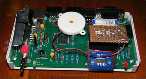
|
||||
| Wajkaj Newbie Joined: 03/11/2012 Location: NetherlandsPosts: 14 |
2012-11-21_183758_RTC1302.zip Hi all, I had some 1302 and a few Xtals that i wanted to test. So i have found the program form Anthony. But the program is not user friendly. You have to fiddle around with bytes and nibbles. So i decided to change this program to make it more friendly for testing. Hope i don't upset Anthony, by changing his program. Only hope this will help others to test there 1302's. The program does not test your input. As long as you give in normal time and date numbers, you are OK. Thanks Anthony for your input. Cheers, Johan. Started with LNW80. |
||||
| ajkw Senior Member Joined: 29/06/2011 Location: AustraliaPosts: 290 |
Johan, No worries with changing the code but you should tag yourself in the program headers as modifying it. i.e Modified by Johan 2012 I am glad that somebody has got some good out of it and is also using the DS1302. Mine has been very reliable but I find I have to update the time a few seconds in every month. I must say my code has come a long way since a year ago, the early version was obviously not user friendly but got the job done in setting the RTC. Part of the original exercise for me was learning how to communicate with other devices. Getting involved in the bits certainly did that. I now also use the 31 bytes of GP Ram also. Cheers, Anthony. |
||||
