
|
|
Forum Index : Microcontroller and PC projects : Maximite Prototyping Board now available
| Page 1 of 2 |
|||||
| Author | Message | ||||
| rhamer Senior Member Joined: 06/06/2011 Location: AustraliaPosts: 174 |
Folks, I now have a Maximite prototyping board kit added to my list of Maximite accessories. Check out my website for more information. 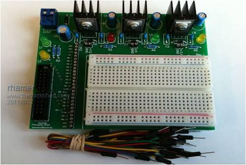
Cheers Rohan Rohan Hamer HAMFIELD Software & Hardware Solutions Makers of the Maximite Expander. http://www.hamfield.com.au |
||||
sparkey Senior Member Joined: 15/06/2011 Location: AustraliaPosts: 819 |
ok rohan when can i have one ..regards sparkey technicians do it with least resistance |
||||
| rhamer Senior Member Joined: 06/06/2011 Location: AustraliaPosts: 174 |
Anytime you like, just order from my website and a few days later it will be delivered to your door. 
Cheers Rohan Rohan Hamer HAMFIELD Software & Hardware Solutions Makers of the Maximite Expander. http://www.hamfield.com.au |
||||
| Ray B Senior Member Joined: 16/02/2007 Location: AustraliaPosts: 219 |
Rohan you just beat me to it.... I was this weekend about to get serious about learning EAGLE PCB design to produce what you have designed, your product even looks like my original sketches - great minds think alike. What is the cost of your complete kit or in short form like just the PCB? Not shown on your web page. Regards RayB from Perth WA |
||||
| sparkey Senior Member Joined: 15/06/2011 Location: AustraliaPosts: 819 |
this board is a must for the maximiter technicians do it with least resistance |
||||
| rhamer Senior Member Joined: 06/06/2011 Location: AustraliaPosts: 174 |
Hi Ray, The full kit is $40 with everything you see in the picture and the 26W interconnecting IDC cable. Postage is $6 anywhere in Australia. I havent offered the board only at this point, but it would be something like $25 which is the same as the rest. To be honest, the full kit is probably better value though, as the parts retail would be more than $15. However given the sales in the first few hours, there may not be any of the first batch left by the end of the weekend. Thanks to all that have purchased. Cheers Rohan Rohan Hamer HAMFIELD Software & Hardware Solutions Makers of the Maximite Expander. http://www.hamfield.com.au |
||||
haiqu Senior Member Joined: 30/07/2011 Location: AustraliaPosts: 152 |
Rohan, Those are some serious looking heatsinks. Nice work. Rob unzip, strip, touch, finger, grep, mount, fsck, more, yes, fsck, fsck, fsck, umount, sleep |
||||
| sparkey Senior Member Joined: 15/06/2011 Location: AustraliaPosts: 819 |
sorry to re coin a phrase but its a pice of art technicians do it with least resistance |
||||
| rhamer Senior Member Joined: 06/06/2011 Location: AustraliaPosts: 174 |
Thank you Rob, you never know what the user may want to drive, so best to be as generous as you reasonably can. Cheers Rohan Rohan Hamer HAMFIELD Software & Hardware Solutions Makers of the Maximite Expander. http://www.hamfield.com.au |
||||
| sparkey Senior Member Joined: 15/06/2011 Location: AustraliaPosts: 819 |
not to put a downer on the heart sinks but where i come from they look pretty standard technicians do it with least resistance |
||||
| sparkey Senior Member Joined: 15/06/2011 Location: AustraliaPosts: 819 |
i think that this will be one of your best incentives as a consumer point of view it has a open possability of easy acsess to all the pinn`s on the maxi also its the best unit i`ve seen so far as a compatability unit...regards sparkey ... technicians do it with least resistance |
||||
| sparkey Senior Member Joined: 15/06/2011 Location: AustraliaPosts: 819 |
technicians do it with least resistance |
||||
| sparkey Senior Member Joined: 15/06/2011 Location: AustraliaPosts: 819 |
i would not be suprized if this unit is one of your best sellers..i wish i had one in my hands right now sincearly sparkey ...power to the people and hardwhare to the consumers technicians do it with least resistance |
||||
| Nick Guru Joined: 09/06/2011 Location: AustraliaPosts: 512 |
I agree. I bought one of these boards the moment I saw it. This is the best way to promote the Maximite for hardware experimentation. I'll be honest and say that interfaceing I2c and Arduino devices to the Maximite, doesn't actually promote the Maximite itself. It just makes the Maximite *yet another* I2c and Arduino interfacing board and one of the more expensive options unless you use Don's board. Wouldn't it be better to encourage the development, experimentation and education in electronic design with circuits 'from-the-ground-up'. Something a bit more than just plugging in ready made modules like 'electronic lego'. This board should be published in Silicon Chip to complement the Maximite project. (Then again, Silicon Chip should have a monthly Maximite column to capitalise the Maximite success. There are many users who don't access this forum and rely on the monthly magazine) |
||||
| sparkey Senior Member Joined: 15/06/2011 Location: AustraliaPosts: 819 |
yes nick i have my inverter just rebuilt with two banks of 3055`s and im waiting till i get this board its defenatley going to the most advanced add on for the maximite ...regards sparkey..and if peops cant see the aspect of what this board is capabelle of then their not tru maximiters technicians do it with least resistance |
||||
| Ray B Senior Member Joined: 16/02/2007 Location: AustraliaPosts: 219 |
One enhancement I'd like to see on interface boards is some form of protection of the microcontroller like using optocoupling of digital I/O lines or at a minimum transistor or whatever type of external semiconductor components as line protection. What type of input protection does the micro chip have from say +12volts from playing around on the protoboard side of things. What is the voltage limits? Alternatively I'd like to see the base MM board with a socket for the microprocessor, impossible to desolder / resolder a new one. 
Comments? RayB from Perth WA |
||||
| sparkey Senior Member Joined: 15/06/2011 Location: AustraliaPosts: 819 |
yes very true i like the possability that you can always use the bread bord adding in a transistor your self its not that diffucult to do thats the whole point of the bread board ..its totally "diy" technicians do it with least resistance |
||||
| sparkey Senior Member Joined: 15/06/2011 Location: AustraliaPosts: 819 |
to rohan i`ve just finished the hub board came up quite nice ..i`m going to get a 19 inch rack mount case so i can house the boards im fitting the rack out with a 18 volt tap from the batterys also wil fit a 12 volt torroid so it can be fed from the mains if the need be required to take it somewhare also like the dip switch function regards sparkey now i just finished the four channell input board this is startin to come together quite nicely...though do have a couple of short beefs ..there were no blue terminal blocks with the kits so at some stage i will need to aquire some of these from you and also i think that even if it means adjusting the kit price a little ...12mm m3 tapped spacers and screw sets... for the boards also the holes in the boards will also have to be changed to a smaller size to accomadate m3 screw sets ..just an oppinion...but on a last note your boards a a pleasure to work with theres no mistake in cct bord quality....sparkey..ah well no rest for the wicked..just built the 4 chanell output board its comming togeather nicely.....also would like to ask y you never ran the 5 volt rail through the hub....??? technicians do it with least resistance |
||||
| rhamer Senior Member Joined: 06/06/2011 Location: AustraliaPosts: 174 |
Just for clarification, these comments are for the Modular Series Boards and not the Prototyping Board. I thought you would have some blue terminals left over from the other board, and given the extra special price, you could use those. I'll send you some. I dont include mounting hardware because everybody will want something different depending on their application and all this will do is raise the price. The mounting holes are designed to take 4mm mounting hardware or 3mm standoffs. Regards Rohan Rohan Hamer HAMFIELD Software & Hardware Solutions Makers of the Maximite Expander. http://www.hamfield.com.au |
||||
| rhamer Senior Member Joined: 06/06/2011 Location: AustraliaPosts: 174 |
Yeah, that is the conundrum, if I provide isolation, then that may not be what is wanted for someones circuit design, but if I don't then the inexperienced might blow it up. For the record, all my other boards provide isolation. You can socket those PIC32 chips but the socket costs more than the whole Maximite and the board needs to be designed to take it. You can however desolder and replace it if you really needed to. If you dont have the equipment or confidence, I'm sure we could work something out if you ever did let the smoke out of one. Cheers Rohan Rohan Hamer HAMFIELD Software & Hardware Solutions Makers of the Maximite Expander. http://www.hamfield.com.au |
||||
| Page 1 of 2 |
|||||
| The Back Shed's forum code is written, and hosted, in Australia. | © JAQ Software 2026 |
