
|
|
Forum Index : Microcontroller and PC projects : Latest Circuit
| Author | Message | ||||
Dinosaur Guru Joined: 12/08/2011 Location: AustraliaPosts: 304 |
Hi all The board that arrived last week does not seem to agree with the circuit on Geoff's site. Are there updates ? I am using it with power from the usb, but have just started looking at using a power supply, and confirming the pin numbers on the ribbon. According to the circuit, I should have 5 vdc on pin 23 and 3.3 vdc on pin 24, but I can't make sense of the voltages. I am using a standard keyed Ribbon connector pre-made for printer port (DB 25).Pin 1 (red Line) agrees with Ribbon supplied. I do have to comment on what was suplied, as it is disappointing that: 1. No Vga pillar nuts to screw the vga in tight. 2. Not even a photo-copied sheet detailing the Jumpers.(particularly since I can't find JP1 to select the power source) The board is marked SM1 PIC32. Regards Regards Hervey Bay Qld. |
||||
sparkey Senior Member Joined: 15/06/2011 Location: AustraliaPosts: 819 |
who supplied your kit and where r u located...regards sparkey ::do you have any old computer cards you could remove two of the screw connectors from that will sole one of your problems technicians do it with least resistance |
||||
| Dinosaur Guru Joined: 12/08/2011 Location: AustraliaPosts: 304 |
Hi all sparkey, I am in Wagga Wagga. The point about the comments was not about how to fix (I know how) but about making the kit user friendly for others. I got it from Dontronics. Regards Regards Hervey Bay Qld. |
||||
| sparkey Senior Member Joined: 15/06/2011 Location: AustraliaPosts: 819 |
ok i have two SM1 boards and if you go to dontronics site the schematic is there under the tctec listing for u to down load other wise go to tctec and you should be able to find what your looking for if you cannoy get a schem just give me a pm with your email and i will send you a copy of the schem and yes the SM1 boards dont have the vga scres dont know why ask don prolly cause the sockets r not supplied with them in the first place but the SM1 is very good i also have an orig altr and a ev embedded they all work fine if you want the whole box and dice you will jave to get an alto one regards sparkey.... technicians do it with least resistance |
||||
donmck Guru Joined: 09/06/2011 Location: AustraliaPosts: 1310 |
Hi Dinosaur, I have added some information about 1/3 of the way down: http://www.dontronics-shop.com/maximite-sm1.html If this doesn't cover all of your queries, please let me know, and I'll tackle it again, until it is correct. Re your query on the nuts, if you have a look at both pictures at the bottom of the page linked to above, you will see the nuts soldered through the board. If yours hasn't got them, then it is a manufacturing problem, which we will address for you. Can you take a quick picture of the missing nuts possibly, so we can make sure that this is what has taken place? Cheers Don... https://www.32v8.com/1 |
||||
| Dinosaur Guru Joined: 12/08/2011 Location: AustraliaPosts: 304 |
Hi all Don, the circuit refers to JP1 being used to select usb or external power. I can't find it. Will try to enclose photo, with the missing pillar nuts in front. I still think that every board should have the minimal information with it, to allow a novice to make it work, ie: Instruction sheet. Maybe I am old school, and don't realise that even novices go and read a site before powering up. But then on the other hand, Male's will read instructions AFTER they get into trouble. Regards 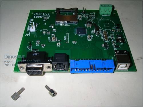
Regards Hervey Bay Qld. |
||||
| donmck Guru Joined: 09/06/2011 Location: AustraliaPosts: 1310 |
Hi Dinousaur, This is what it says on my web page: [code] Schematic differs from the original Silicon Chip article. There is no jumper to select power source, as this is done automatically using diodes. U2 Sound Output. U4 Video Select. U5 Video Ouput. Schematic Update from Geoff Graham: In the schematic, the IDC pin numbers of the 26 pin I/O connector are incorrect. The correct schematic can be found here (this diagram also contains a number of other minor corrections). If you are connecting an external circuit to this connector the best approach is to refer to the image of the I/O connector in the April 2011 issue of Silicon Chip (Fig 5) or the Maximite User Manual as they are correct. [/code] I would think Olimex are the largest board supplier in the world today, and SparkFun would be the largest retailer of these boards. In fact SparkFun started off by selling only Olimex boards. I have never seen a sheet of paper come with any Olimex board. It is the way of the world today. Thanks for the picture, I can clearly see what you are saying now. I just had a look at three notebooks and none of them have a VGA cable securing method at all. I am running on a fast Core i7 notebook as my main PC these days, and it has no provision for securing screws. I'll ask Richard, the manufacturer about this. Cheers Don... https://www.32v8.com/1 |
||||
| Dinosaur Guru Joined: 12/08/2011 Location: AustraliaPosts: 304 |
Hi all I just had a look at three notebooks and none of them have a VGA cable securing method at all.
Don, I have never based my performance on the performance of others, so the above comment does not make it right. I have seen to many screens / boards go south as a result of spiking on a loose vga connector.
I am running on a fast Core i7 notebook as my main PC these days, and it has no provision for securing screws. But hey, this was meant as a suggestion, so I'll leave it at that. Regards Regards Hervey Bay Qld. |
||||
tectec Newbie Joined: 24/08/2011 Location: AustraliaPosts: 1 |
Hi, Pin 1 is pin 1 on the maximite 26 pin header diagram. Pin 1 is not pin 1 on the ribbon cable or the plug. Refer to the pin-out of the Maximite in the maximite manual. The Maximite SM1 has the circuit of the Maximite SM1. refer to the circuit diagram of the Maximite SM1. Power supply is automatic. Plug in USB, or any power supply from 7V to 20V, or both. As per the circuit diagram there are Schottkey diodes so jumpers are not needed. The VGA connector is standard. 
|
||||
