
|
|
Forum Index : Microcontroller and PC projects : SPI and the Maximite
| Page 1 of 2 |
|||||
| Author | Message | ||||
| MM_Wombat Senior Member Joined: 12/12/2011 Location: AustraliaPosts: 139 |
Trying to connect a 74HC595 Shift register to the Maximite. Following an Arduino tutorial, that showed similar tx, and rx to that of spi arduino: shiftOut(datapin, clockpin, MSBFIRST, coldata) maximite returnvalue= SPI(tx,rx,clk,data) My question is, the Maximites maximum speed is 500 KHz (500,000 Hz) but the 74HC595 has a speed of 100 MHz (100,000,000 Hz) a factor of 200x slower.. Will that be a problem? Keep plugging away, it is fun learning But can be expensive (if you keep blowing things up). Maximite, ColourMaximite, MM+ |
||||
| Olimex Senior Member Joined: 02/10/2011 Location: BulgariaPosts: 226 |
no problem to clock faster device with slower clock SPI |
||||
| MM_Wombat Senior Member Joined: 12/12/2011 Location: AustraliaPosts: 139 |
Ok thanx Olimex Keep plugging away, it is fun learning But can be expensive (if you keep blowing things up). Maximite, ColourMaximite, MM+ |
||||
| MM_Wombat Senior Member Joined: 12/12/2011 Location: AustraliaPosts: 139 |
WooHoo Got it working on two 74HC595 chips, one feeds into the other. When I shift one with a byte, the other receives the previous byte. Think I found a bug though. Will need to email Geoff, and see... if only I could get it to work with the BC547 transistors, so I can use the 12 volt to power the led string/strip. I think this is a drawing of the circuit..the resistors and led's would be replaced with an LED strip of about 15 led's. Once I can get it to work on a breadboard. 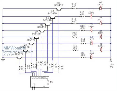
Don't worry about the chip at the bottom, I just used it because it has eight outputs. When I turn on the 74HC595, All the led's light up dimly, and the chip doesn't work properly ( not at all even). If I keep the outputs, feed them into reversed led's and resistor's that go to ground then the 74HC595 works perfectly.... Any suggestions for a Newbie.. Keep plugging away, it is fun learning But can be expensive (if you keep blowing things up). Maximite, ColourMaximite, MM+ |
||||
CircuitGizmos Guru Joined: 08/09/2011 Location: United StatesPosts: 1427 |
Is your ground common between your digital circuit and the 12V supply? Micromites and Maximites! - Beginning Maximite |
||||
| MM_Wombat Senior Member Joined: 12/12/2011 Location: AustraliaPosts: 139 |
@ CircuitGizmos No. could it be that simple? Newbie mistake.. Keep plugging away, it is fun learning But can be expensive (if you keep blowing things up). Maximite, ColourMaximite, MM+ |
||||
| CircuitGizmos Guru Joined: 08/09/2011 Location: United StatesPosts: 1427 |
Yes. Think of it this way: The transistor is acting as a switch to complete the 12V current path between collector and emitter. To do this, there has to be some current flow through the base and emitter. To make that be a loop, the ground of the digital circuit needs to be common to the transistor's 'ground' - in this case the emitter. Mentally take away the bright LEDs and 12v supply and think of the transistor as an LED you want to turn on. If you think of it that way, you know that a single connection to this imaginary LED isn't going to cut it. Your mental picture is a loop of current from output through 1k through imaginary LED and back through ground. The base/emitter connection replaces that imaginary LED. Micromites and Maximites! - Beginning Maximite |
||||
| MM_Wombat Senior Member Joined: 12/12/2011 Location: AustraliaPosts: 139 |
ok, Thanks very much, will try that tomorrow.. Keep plugging away, it is fun learning But can be expensive (if you keep blowing things up). Maximite, ColourMaximite, MM+ |
||||
| MM_Wombat Senior Member Joined: 12/12/2011 Location: AustraliaPosts: 139 |
Just before I do anything I just wanted someone to check my circuit.. 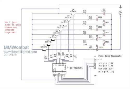
Also , I think the current drain is causing the Maximite to heat up too much. Should I get/build another Power source? Or once I get the transistors to work ok, then the current will drop? Keep plugging away, it is fun learning But can be expensive (if you keep blowing things up). Maximite, ColourMaximite, MM+ |
||||
| CircuitGizmos Guru Joined: 08/09/2011 Location: United StatesPosts: 1427 |
Ground-wise that looks good. Are you supplying the '595 from the 3.3 of the Maximite? You might want a separate 3.3V regulator/supply. (With common ground...) Micromites and Maximites! - Beginning Maximite |
||||
| CircuitGizmos Guru Joined: 08/09/2011 Location: United StatesPosts: 1427 |
If you are interfacing to unknown circuits, you can provide a little bit of protection to your Maximite by using 100 ohm series resistors on the signal lines. This applies to this circuit and most others. In this and most cases signal lines are hardly affected by the series resistor, but it offers some protection against mishap such as a short to ground. Micromites and Maximites! - Beginning Maximite |
||||
| MM_Wombat Senior Member Joined: 12/12/2011 Location: AustraliaPosts: 139 |
Thanks CircuitGizmos Yes, I think I might purchase a kit from altronics for a variable voltage power supply, that has max current of 1.5A . 3,6,9,12 V out... Kit # K 3220 I assume I just power the new psu from the 12v line.. Thanks for the heads up on the signal lines ( I've already fried one Maximite ). Might need to get another processor chip and replace... Cheers MM_Wombat On the bug in the SPI returned byte. It seems that the result has been rolled to the left bitwise by one bit. So if I send a 6 to the '595 chip. Next byte sent returns my previous byte, but now it is a 12. If I send anything over a 128 then the returned byte is an ODD Number.. ie 6 returns a 12 47 returns a 94 128 returns a 1 237 returns a 119 So I devised this fix (as well as emailing Geoff with a bug report) pin(17)=0 pause 1 junk=SPI(18,19,20,datasent) pause 1 pin(17)=1 If ( junk mod 2) = 1 then junk= INT(junk/2)+128 Else junk= junk/2 Endif Keep plugging away, it is fun learning But can be expensive (if you keep blowing things up). Maximite, ColourMaximite, MM+ |
||||
| CircuitGizmos Guru Joined: 08/09/2011 Location: United StatesPosts: 1427 |
I have to skedaddle. I can't work this out in my head, but is this a situation of clock phase not being right? Micromites and Maximites! - Beginning Maximite |
||||
| MM_Wombat Senior Member Joined: 12/12/2011 Location: AustraliaPosts: 139 |
I had two '595's connected together, and the second chip, which receives the first chips return byte, was always just one step behind the first chip. It was only fudging the byte, when it was returned to the maximite. I don't understand the clock phase thingy, but I did find I had to add a pause of 1 millisecond to read the return byte consistently... Thanks CircuitGizmos for your help.. Keep plugging away, it is fun learning But can be expensive (if you keep blowing things up). Maximite, ColourMaximite, MM+ |
||||
| MM_Wombat Senior Member Joined: 12/12/2011 Location: AustraliaPosts: 139 |
Well I have almost finished, my little test. spi works ok. Now to work on the input from the user.. 
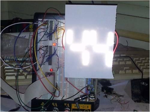
Had to put some paper over the led's so I could take the photo.. The test board has 3 leds, per leg. Finished product will have 15. The Maximite sends the data, via SPI to the 74HC595 chips, 2 in series. Those chips send data to the darlington transistors (ULN2003AN). These switch the current through the 12 V to power the led's. Thanks everyone for any feedback they have given me. Keep plugging away, it is fun learning But can be expensive (if you keep blowing things up). Maximite, ColourMaximite, MM+ |
||||
| DaveT Newbie Joined: 22/01/2012 Location: AustraliaPosts: 2 |
MMWombat - The 74HC595s and the ULN2003s will all run upto 15 volts. Just connect their supply pins to the 12 volts of the LED supply and not the 3.3 volts from the DM/MM. Have the grounds connected common and your 3.3 volt current will drop to normal levels. No need for an extra supply unless the LED supply is too light.  VK2TDT - There are 10 types of people. Those that understand binary & those that don't! |
||||
| MM_Wombat Senior Member Joined: 12/12/2011 Location: AustraliaPosts: 139 |
@ DaveT The datasheet for the 74HC595N chips I am using state the maximum is 6V. Regards MMWombat Keep plugging away, it is fun learning But can be expensive (if you keep blowing things up). Maximite, ColourMaximite, MM+ |
||||
| proftim Newbie Joined: 09/03/2012 Location: United StatesPosts: 1 |
If you are going to use 15 leds in each string in series you are going to need a supply voltage of at least 22 volts. You could use (three series groups of 5 leds each in series with an appropriate resistor. Then place the three series groups in parallel for use with 12 volts. |
||||
| MM_Wombat Senior Member Joined: 12/12/2011 Location: AustraliaPosts: 139 |
I am using an led string, that only needs 12V to run, as only 3 leds, are running off of 1 current limiting resistor. Each digit segment has 5 of these groups of three, totalling 15 led's. So I already, am using as you suggest! The previous pics had one section of three as a breadboard prototype. The 2nd prototype Digiboard ( 1000mm x 800mm ) can be seen here(37.1 Mb) , with the floating dollar signs changing position, as the end digit is changed via a membrane switch which inputs on 5 of the Maxi-mites pins, and a small chaser flashing alternately in the top right. In the completed version, the chaser would, of course, encompass the whole board. These operate from the decimal point , as it is not needed in this situation (layout)... The leds are quite bright so I had to fit cardboard and paper over them to diminish them enough for the video, so the dollar signs are unrecognisable. MM_Wombat Keep plugging away, it is fun learning But can be expensive (if you keep blowing things up). Maximite, ColourMaximite, MM+ |
||||
| Shaz_Au Newbie Joined: 31/10/2012 Location: AustraliaPosts: 11 |
Hi MM_Wombat, I was wondering if you would mind posting your source code for the basic interface to the shift register. I've looked at some of the code from your DMD and larger displays and it just went straight over my head! At this stage I'm just trying to emulate what is in the Arduino Shift Out tutorials so I can get my head around it. Thanks, Shannon |
||||
| Page 1 of 2 |
|||||
| The Back Shed's forum code is written, and hosted, in Australia. | © JAQ Software 2026 |
