
|
|
Forum Index : Microcontroller and PC projects : (DM) ULN2003 based stepper motor [solved]
| Author | Message | ||||
mariae71 Regular Member Joined: 22/08/2012 Location: SwedenPosts: 43 |
Hi all, I'm Maria from Sweden and new to micro controllers but eager to learn. :) Have a DuinoMite Mega and some ULN2003 stepper motor drivers and a couple of unipolar (five wires) stepper motors from scrapped scanners/printers. Problem is, I'm not sure where to put current on the stepper motor driver, so thought I ask if any of you could help. I attach photo of the driver so you see it. 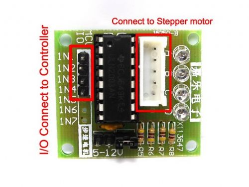
I suspect i should put either 5v or 12v on either of the terminals labelled so, and leave the unused one jumpered as is, but to afraid to just test it in case it fries my DuinoMite. (have another DuinoMite still boxed if this one fry) edit: Perhaps the back with all traces are good to include. :) 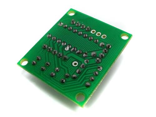
edit again: sorry, disregard all this, I see now it says 5 to 12v... How embarrassing... Pretty tempted to delete this post now... Well...  2 x DuinoMite Mega 1 x DuinoMite eMega |
||||
| Frank N. Furter Guru Joined: 28/05/2012 Location: GermanyPosts: 1131 |
Hello Maria, take a look at: http://ssecganesh.blogspot.de/2008/05/driving-stepper-motor- using-uln2003.html Frank |
||||
| mariae71 Regular Member Joined: 22/08/2012 Location: SwedenPosts: 43 |
Much thanks for the link Frank, I managed to get the driver to output signal in the right sequence and the motor to spin, but I think two or more pins between the driver and motor is in wrong place, because motor sometimes misses steps or run a bit jerky... Awesome with the leds on the driver so one can see the sequence... :) The illustration on the link you provided should be a great help to put wires in right order on the motor. :) 2 x DuinoMite Mega 1 x DuinoMite eMega |
||||
| mariae71 Regular Member Joined: 22/08/2012 Location: SwedenPosts: 43 |
I change my mind, I'm now pretty sure i have the motors wired up correct, because they actually run silk smooth with a 5ms pause between steps as fastest, only not so much torque, but that's what to expect I guess... So... Now I need a driver for bipolar stepper motors, but that's for another day, or year... 2 x DuinoMite Mega 1 x DuinoMite eMega |
||||
| Frank N. Furter Guru Joined: 28/05/2012 Location: GermanyPosts: 1131 |
Hello Maria, take a look on http://www.pololu.com/catalog/product/1182 or http://www.pololu.com/catalog/product/1183 for a bipolar motor driver. I think 2A is too much for this layout without cooling, but it seems to be a very interesting driver chip. I have one of the Pololu A4988 Stepper Motor Driver Carrier at home but had not yet time to check it out... Frank |
||||
| mariae71 Regular Member Joined: 22/08/2012 Location: SwedenPosts: 43 |
Hello again Frank, Once again, thanks for the tips, I actually ordered a stepper motor controller called Big Easy 2 or something similar last night... Also ordered a stack of ULN2003 chip, since I fried one of the transistors in one of the chips... Might be able to use the chip anyway if I modify the card and exchange the traces, but, it really does not matter, because 7 ULN2003 chip only cost around 1� from my supplier. Might be able to use the broken arrays to control some relays instead. :) Also read somewhere that one can stack two or three ULN2003 on top of each other to increase the amperage tolerance, can someone confirm this? 2 x DuinoMite Mega 1 x DuinoMite eMega |
||||
| Frank N. Furter Guru Joined: 28/05/2012 Location: GermanyPosts: 1131 |
Hello Maria, it is not a good choice to stack different ULN2003 together. ...but it is possible to increase the allowable current with shorting two outputs of one ULN2003! Different ULN2003 have different transistors with different values and different temperatures - you will get a unequal current through the transistors! One output must deliver more current than the other! The transistors in one ULN2003 have the same tolerances and aprox. the same temperatur => you can shorting two or three outputs (and inputs) from the same ULN2003 to increase the allowable current! Frank |
||||
| mariae71 Regular Member Joined: 22/08/2012 Location: SwedenPosts: 43 |
But if I stack four identical ULN2003 ontop of each other, or is every ULN2003 from same type and batch different? Because the ULN2003 only have 7 transistors i cannot short the pins on one chip to double since i need 8 transistors to do that. 2 x DuinoMite Mega 1 x DuinoMite eMega |
||||
Downwind Guru Joined: 09/09/2009 Location: AustraliaPosts: 2333 |
Just use 4 larger single transistors to drive the uni-polar motor, the DB681 darlington transistor is a 4 amp transistor and is a common choice in my projects. Sometimes it just works |
||||
TassyJim Guru Joined: 07/08/2011 Location: AustraliaPosts: 6541 |
The temperature inside each IC would be different. The one on the bottom would have less cooling so its gets hotter. The internal temperature within each IC would be reasonably consistent. Jim VK7JH MMedit |
||||
| Frank N. Furter Guru Joined: 28/05/2012 Location: GermanyPosts: 1131 |
@ TassyJim: Exactly! I developed a simple driver circuit for unipolar motors with SMD-mosfet transistors since years ago... Mosfets are a better choice then Darlingten transistors... Take a look at: http://www.wegold.de/html-d/produkte/katalog-detail.php?id=1 391 or http://www.youtube.com/watch?v=cgf1O6Ua7G8 This machine works with my circuit. There are 6 linear-actuators (unipolar stepper motors) inside, controlled by keyboard... The generated force of each motor is 100N! ...with little SO23 Mosfet transistors... Frank |
||||
| mariae71 Regular Member Joined: 22/08/2012 Location: SwedenPosts: 43 |
Nice! That's very impressive! :) Surface mounting is however way out of my league... I have a soldering pen and some empty THT prototype boards, that's it... Will look for THT equivalents of those Mosfet transistors at my local electronics shop. Thanks, you are all very helpful. :) Cannot find the DB681 in my local shop, but I guess that DB679 would work as well? Only using 12V and 1A. What resistors do you use with your drivers? 2 x DuinoMite Mega 1 x DuinoMite eMega |
||||
| Downwind Guru Joined: 09/09/2009 Location: AustraliaPosts: 2333 |
The DB679 should work ok and it has a built in snubber diode so makes it easy there too. A 1K resistor on the base pin should be suitable, but i dont know the max output rating for the I/O of your processor so you will need to check you dont exceed the max mA rating for the I/O pin. Using a 1K resistor should be around 10mA on the I/O pin and would be within its range i would expect. Sometimes it just works |
||||
| ronee Newbie Joined: 08/01/2012 Location: CanadaPosts: 20 |
The better choice would have been the ULN2803 which has 8 sections. Much easier then to parallel two sections for double the output. Ron P |
||||
| mariae71 Regular Member Joined: 22/08/2012 Location: SwedenPosts: 43 |
Nice! I ordered a couple of those the other day... :) Also, on a Piezo Driver card from an old broken huge Howtek printer that got slaughtered for rare electronics, I found four ULN2823A, seems to have 8 transistors as well... Other nice stuff on that card is 32 variable resistors, four 10K resistor arrays and four chips called SN74LS24N. Still planning to test all other suggestions in this thread, I just have to learn a bit more first. I'm very grateful for all help and advice... Thanks! :) edit: spelling... edit2: If anyone is interested about what's happened so far... This is a photo of the proto one I made with two ULN2803, with 4 sections in parallel per lead, very satisfied with it, stays room tempered all the time with 12V 650mA, and should handle at least 2A... 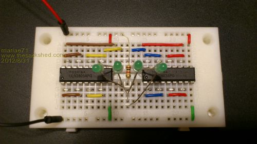 2 x DuinoMite Mega 1 x DuinoMite eMega |
||||
| The Back Shed's forum code is written, and hosted, in Australia. | © JAQ Software 2026 |
