
|
|
Forum Index : Microcontroller and PC projects : MM - Relay Control Poject
| Page 1 of 2 |
|||||
| Author | Message | ||||
| mattma Newbie Joined: 01/10/2012 Location: AustraliaPosts: 25 |
Hi All This is my first post but I've been reading the forum for a while so I'm excited to finally have something to share. I recently built a monochrome Maximite and decided to make use of it in one of my other pass-times which is building composite kiteboards. The kiteboards are epoxy, fibreglass and carbon fibre constructions and so the c. 48 hour curing process usually involves working with vacuum bagging and elevated temperatures. So I decided to put some effort into making a process controller using the Maximite and have today largely finished it 
The controller has 4 temperature sensors, 2 x 0-30 psi pressure sensors on board and 3 relays that can switch 1 kw loads such as the vacuum pump, silicone heating blankets or lamps. The Maximite then provides the intelligence part of the controller. The circuit was designed by someone I hired on Freelancer.com (which was a fun experience in its own right). To my horror the design came back using mostly surface mount components which I had never worked with before and so after a few hours on YouTube learning how to solder the suckers (and a month waiting for all the bits to arrive from Element14) I had a crack at it. To my amazement I didn't fry anything along the way and was suffering just a single short which fortunately was in not in a sensitive area. The software took on a bit of a life of its own. Very refreshing reminder of why object oriented is good!! However the MMEdit program helped make the process much easier (although adding an intellisense to it would be gold!). The software does the following: i) Reads and stores all the data in a circular queue that could be saved to disk. ii) Let you set absolute on/off trigger levels for each relay as well as creating triggers based on the difference between sensor readings. iii) Plots simultaneously on 2 separate charts so that you can view on a short time scale and long time scale chart iv) Run test routines and misc config setting that can be saved to disk. Here are a couple of snaps of the finished board, cabinet and the screen shots. 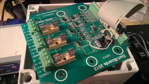
close up of board. A slight issue with the PCB board meant a work around on the pressure sensor ( 40% of the cost of the project in that one component!) 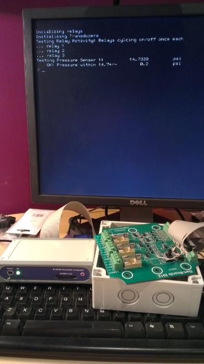
The very first test 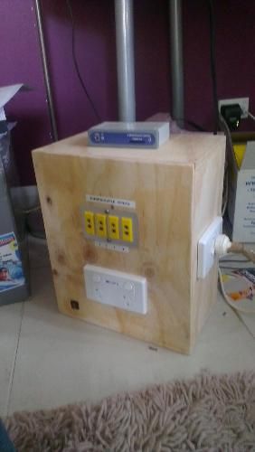
"Generous" Cabinet to house it. Has 4 thermocouple inputs for temp sensors and 3 240v sockets connecting to the relays. 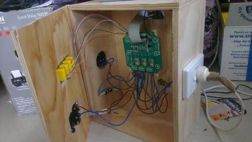
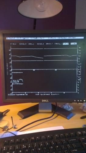
Screen shot of the charting function showing the split screen short and long time scale plots. The traces wrap at the end of the chart and overwrite the previous sections so you can always see a period equal to the time scales. The code up at 1200 lines with most of it dedicated to the charting and configuring the controller and the charts. It would be relatively easy to adapt the code to make a general purpose charting tool. In case its useful to anyone I'll upload the code in a separate post. More details on my blog Cheers Matt |
||||
| mattma Newbie Joined: 01/10/2012 Location: AustraliaPosts: 25 |
... here's the schematics+BOM for the MM relay module and the code for the MM for reading and plotting the data. It quite generic so hopefully can find some reuse. The comments hopefully make it clear what's what but happy to clarify anything that's a bit off. Cheers Matt 2012-10-01_135512_Cont.zip |
||||
CircuitGizmos Guru Joined: 08/09/2011 Location: United StatesPosts: 1427 |
That is a great looking project! Thanks for sharing all of that. Micromites and Maximites! - Beginning Maximite |
||||
| Geoffg Guru Joined: 06/06/2011 Location: AustraliaPosts: 3363 |
This is just awesome. It is a large project and you have everything completed, packaged and working. Amazing and congratulations - it must have taken a lot of time. Thanks for the words and photos, seeing projects like this helps makes the whole Maximite effort worthwhile. Geoff P.S. Freelancer.com is an interesting concept and it seemed to have worked well for you. Geoff Graham - http://geoffg.net |
||||
| mattma Newbie Joined: 01/10/2012 Location: AustraliaPosts: 25 |
Thanks very much! I had a great time doing it and am just amazed at what a great device the Maximite is. Its been around 25 years since I had done anything with electronics and even then it was a beer powered radio. One thing that is just great about the Maximite is that it makes so much sophisticated control and interaction with the world so accessible to people like me who are short on technical skills but big on ideas. Brilliant work Geoff! I have another couple projects on the drawing board with the MM as the grey matter for them: logging strain sensor data from the kiteboard while in use on the water and a device for helping with sprint training by measuring stride rate and exerted force - It sort feels like I've got a hammer and so everything is starting to look like a nail. Cheers |
||||
| rodent59 Newbie Joined: 02/03/2012 Location: AustraliaPosts: 7 |
If I've interpretted your circuit diagram and your photographs correctly, may I raise a word of caution? It appears that you have an incoming 240V supply (left of photo) supplying the 3 x 240V circuits via the relays. There does not appear to be any earth conductors to the socket outlets. AS3000 requires that all socket outlets have the earth connected. Perhaps I have misinterpretted your information? If so, apologies. [Edited from earlier post where I probably had my interpretation wrong.] |
||||
| mattma Newbie Joined: 01/10/2012 Location: AustraliaPosts: 25 |
Hi Rodent59 Thanks very much for posting me on this. You are right that the photos don't show any earth connections and this was a v. dangerous oversight that I am in the process of fixing. The earth for the 240V input is just available and I'm going to install another bus bar connector and wire up the earth on each of the sockets. I have to admit to a moment of ignorance when I was making the housing. I thought to myself there's no way a wooden box could be be live. Which is true in the same way as saying it doesn't rain in my house is true but also not the point 
AS3000 is Australian Standards? Cheers Matt |
||||
| rodent59 Newbie Joined: 02/03/2012 Location: AustraliaPosts: 7 |
Hi Matt, AS3000 is the Australian and New Zealand Wiring Rules(Actually AS/NZS 3000:2007 Electrical installations (known as the Australian/New Zealand Wiring Rules)). Its application is mandatory in all states. "Clause 5.4.2 Socket-outlets The earthing contact of every socket-outlet shall be earthed." Hope this helps. Rod. |
||||
centrex Guru Joined: 13/11/2011 Location: AustraliaPosts: 320 |
Hi Mattma A brilliant project, but I have a couple of questions. At the start of the software you say you are using pins 11, 12 and 13 for the relays and then you use setpin 18,19 and 20 for digital outputs, this does not seem to gel with the circuit diagram. Or am I missing something. The same goes for the thermocouples the pins you allocate arent the same as the circuit diagram. Other than that a complex well annotated piece of software. The info on your blog is also very informative. Regards Centrex. Cliff |
||||
| mattma Newbie Joined: 01/10/2012 Location: AustraliaPosts: 25 |
Hi Centrex Thanks Centrex. Mate, well spotted! The pins being set in the software are the correct ones. Unfortunately there were a couple of mistakes in the PCB layout. The relays and the 26 way IDC connector the bottom views were confused for the top views when inserting the pin assignments. This meant that the relays needed to be inserted from the underside of the PCB (they have offset pins - this is why they aren't visible in the pictures) and so too should the connector have been except I discovered it too late. The work around was to change the pin assignments. The only problem with this was that one of the pins on the circuit diagram earmarked for relay control was actually connected to 3.3V. This meant I had to move the wire in the ribbon cable so it connected another pin. I think installing it on the underside would have been cleaner. There was also another error on the PCB with the pressure sensor the output should have been on pin 3 but was drawn as being on pin 4. ( The work around being the wire hookup wire you can see) I have the gerbers and some other documentation on the controller if you are interested in them. I don't have any PCB cad software to fix the issues but if you do your more than welcome have them. Cheers Matt |
||||
| mattma Newbie Joined: 01/10/2012 Location: AustraliaPosts: 25 |
Thanks Rod.Much appreciated! |
||||
| vasi Guru Joined: 23/03/2007 Location: RomaniaPosts: 1697 |
Hi Matt, Now, that you have seen the errors and know how the PCB should be, you have courage to start designing your own? Maybe using DipTrace? I think making this the next target, will make the project even more exciting. Vasi Hobbit name: Togo Toadfoot of Frogmorton Elvish name: Mablung Miriel Beyound Arduino Lang |
||||
| centrex Guru Joined: 13/11/2011 Location: AustraliaPosts: 320 |
Hi Mattima For me the software crashes with a report that a file hasnt been opened. May be because I dont have the interface board connected, but I would have thought it would have run just with no connection values. I would just like to see the graphs in operation. Is there any way to test with test values inserted. All very interesting. centrex Cliff |
||||
| mattma Newbie Joined: 01/10/2012 Location: AustraliaPosts: 25 |
Hi Centrex Sorry for slow reply. For some reason I didn't get an email letting me know there were more post. Thanks for letting me know. I'll do some quick checks. It will run without the RCM connected but it won't display any charts. I'll add a simulation mode to it so you can see the charts in action. Can you post the error message. Its most likely that due the program trying to read the triggers or chart default files which are not present. Which happen at start up. I have another version with data exporting including and will post this evening. Cheers Matt |
||||
| mattma Newbie Joined: 01/10/2012 Location: AustraliaPosts: 25 |
Hi Vasi Thanks for the tip. It looks like there is a trial version I can use to fix it up. Do you know of any freeware PCB cad software that is worth trying? Cheers matt |
||||
| jebz Regular Member Joined: 13/06/2011 Location: AustraliaPosts: 79 |
RS Design spark PCB designer has a good range of import and export capabilities. http://www.designspark.com/pcb?utm_source=dscaro&utm_medium= dscaro&utm_campaign=dscaro Version 4 should be out soon. |
||||
| mattma Newbie Joined: 01/10/2012 Location: AustraliaPosts: 25 |
Hey Centrex, Here is the latest version of the program for the controller. I ran into the memory limit for editability mentioned in the post by Graeme Meager and so I've had to drop a few comments and removed the table display of the live readings which was largely redundant anyhow. I've fixed that issue you raised. It was due to the absence of the chart defaults file CDef.txt. I've fixed it so that it has defaults set in the code and overwrites them only if it finds the CDef.txt file. I've also added a demo mode so that you can see the charts in action. To set it to demo mode, scroll down to the Mail Loop (search for 'main loop').There is a variable called demo_mode$ which is set to false by default. Set this to 'true' and it will plot dummy data for the 4 temperature sensors which will be plotted on the left hand axis. New feature in the program is an export function to save the data to disk. Press '4' to start logging and saves it to a file called DataX.csv where X is a number which it automatically assigns. The defaults for this logging feature is under the menu option 3 -> Defaults along with the chart defaults. There are two modes for logging. 'sample' - saves each nth reading where n is an integer between 1 and 120. The other option is 'adaptive' which logs the data only when one of the sensor readings changes by a user defined amount. This is designed for long monitoring jobs to save disk space. It will record the interesting features in the sensor readings and otherwise only make one recording each 120 readings ( the size of the circular queue). 2012-10-09_130555_MMcontroller.zip Briefly, to see the plots in action i) set demo_mode$="true" ii) Defaults will be loaded for chart config but you can change using menu option 3->D ii) run it and press menu option 3->p and press 'y' to reset elapsed timer iii) press menu option 2 to start monitoring the sensors and displaying on screen. iv) Menu option 4 starts the logging of data to disk as a csv file which can be opened in MS Excel. If using adaptive monitoring its best to plot it in excel using an x-y scatter plot as the samples will be unevenly spaced and so normal line graphs will distort the time scale. Cheers Matt |
||||
| mattma Newbie Joined: 01/10/2012 Location: AustraliaPosts: 25 |
Great. Thanks! |
||||
| vasi Guru Joined: 23/03/2007 Location: RomaniaPosts: 1697 |
Then, lets wait for the version 4... I'm curious to see how they will counter attack Eagle, KiCAD and DipTrace... I have nothing against (and I'm not a fan boy) a free and better application. Matt, you can have a maximum of 500 pins (on DipTrace) as a limit for free - no limit on board size. It is the most user friendly PCB designer from all. I use also other programs, but this is what I will recommend to you (they also have great video tutorials). Hobbit name: Togo Toadfoot of Frogmorton Elvish name: Mablung Miriel Beyound Arduino Lang |
||||
| MicroBlocks Guru Joined: 12/05/2012 Location: ThailandPosts: 2209 |
I like diptrace also, compared to others it is very intuitive. You will be making boards in no time. Microblocks. Build with logic. |
||||
| Page 1 of 2 |
|||||
| The Back Shed's forum code is written, and hosted, in Australia. | © JAQ Software 2026 |
