
|
|
Forum Index : Microcontroller and PC projects : Adding CAN to CGCOLORMAX
| Page 1 of 5 |
|||||
| Author | Message | ||||
Lopezjm2001 Regular Member Joined: 08/07/2012 Location: AustraliaPosts: 42 |
I have made a preorder of the CGCOLORMAX. I want to add CAN to it. Not sure whether to add a CAN shield and use SPI. or just add the CAN circuitry. So I am asking the brainiacs on this forum as to which approach would be the better with the plan of using mmbasic 4.0 with CAN commands. Thanks in advance. Lopez |
||||
bigmik Guru Joined: 20/06/2011 Location: AustraliaPosts: 2981 |
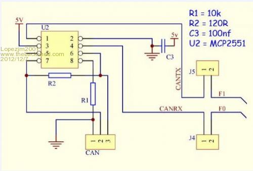
I believe Geoff is going to bring out a version of MMBasic that supports CAN using PIC32 Pins F0 and F1. This is the circuit I have used on the UBW32-MCC PCB. It would be a piece of cake to wire this onto the proto area of the CGCOLORMAX. J4 and J5 are jumpers, and if you are going to always want CAN they can be simply ignored and wired across. CAN header is GND, CAN-H, CAN-L (pins 1,2,3). R2 is Bus termination and can be ignored if not required. 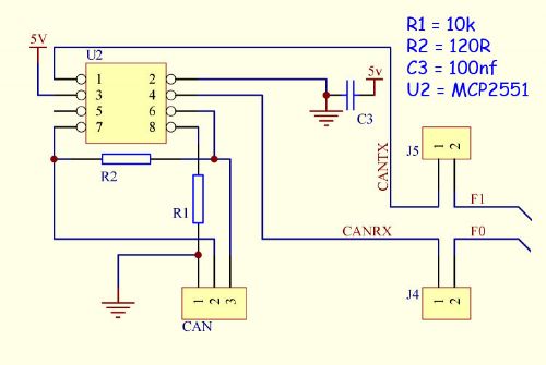
I got the circuit from the Duinonite range of `mites so I assume that it works ok as many people are using DM for CAN. PS. The pinout of U2 (in the schematic) is NOT drawn the same as the physical IC numbering convention. Mik Mick's uMite Stuff can be found >>> HERE (Kindly hosted by Dontronics) <<< |
||||
| Lopezjm2001 Regular Member Joined: 08/07/2012 Location: AustraliaPosts: 42 |
Thanks Mick, This is the way I want to go. The circuit diagram you provided is the same as that used by the Duinomite Mega CAN circuit that uses a PIC32 connecting to pins 58(RF0) and 59 (RF1). I am already running mmbasic 4.0 with CAN commands that were provided by John Harding. Hopefully it should be straight forward to get this done. Lopez |
||||
| Lopezjm2001 Regular Member Joined: 08/07/2012 Location: AustraliaPosts: 42 |
Adding my own circuitry to the prototype area as shown above is the option I want to go with but I am not 100% sure it will work with the mmbasic 4.0 with John Harding's CAN commands. As this board CGCOLORMAX1 is not exactly a color maximite and little documentation on it is available. So looking at the color maximite and the Duinomite Mega they appear to use different pins for CAN TX and CAN RX. DUINOMITE MEGA - uses pins 58 and 59. 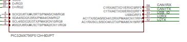
COLOR MAXIMITE - uses pins 87 and 88 (according to BigMick from THE BACKSHED) 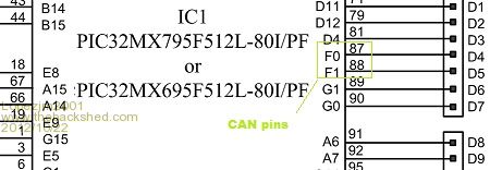
So due to the difference in pin numbers I am optimistically hopefull that the MM basic 4.0 with CAN commands will work. Any opinions? Lopez |
||||
| MicroBlocks Guru Joined: 12/05/2012 Location: ThailandPosts: 2209 |
Lopezjim, Both systems use different chips! The colour maximite is build with a 512L (notice the L on the end of the partnumber) the 100 pin version. For can bus these pins canbe used: C1RX 87 bus receive pin C1TX 88 bus transmit pin C2RX 90 bus receive pin C2TX 89 bus transmit pin AC2RX 8 Alternate bus receive pin AC2TX 7 Alternate bus transmit pin The alternate for C1 (CAN1) has a pin that is already used for the sd card. If can1 is used on the DM then it corresponds to the same internal peripheral on pins 87 and 88 on the colour maximite. Microblocks. Build with logic. |
||||
| Lopezjm2001 Regular Member Joined: 08/07/2012 Location: AustraliaPosts: 42 |
Thanks. Who thought one letter made so much difference. Typical Newbie mistake I guess. Lopez |
||||
CircuitGizmos Guru Joined: 08/09/2011 Location: United StatesPosts: 1427 |
I was this close >< to adding CAN circuitry to the ColorMax. I don't know what the language support would include, though. Micromites and Maximites! - Beginning Maximite |
||||
donmck Guru Joined: 09/06/2011 Location: AustraliaPosts: 1314 |
I had to talk Mick into adding CAN to the UBW32-MCC-PCB, as I was keeping any eye on the thread at: http://priuschat.com/threads/my-duinomite-mega-canview-v4-eq uivalent-project.112429/page-16 Felt they would get there sooner or later. There is a question on that thread (the current last one) that you may be able to answer Rob. Don... https://www.dontronics.com |
||||
| CircuitGizmos Guru Joined: 08/09/2011 Location: United StatesPosts: 1427 |
From the perspective of the software, the hardware is the same. In other words the same microprocessor pins connect to the same MaxiMite/Arduino headers in both the Colour MaxiMite and the CGCOLORMAX1 (ColorMax). Micromites and Maximites! - Beginning Maximite |
||||
| bigmik Guru Joined: 20/06/2011 Location: AustraliaPosts: 2981 |
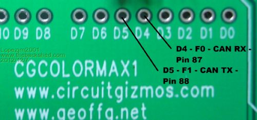
Lads/Lassies, Before adding CAN support to the UBW32-MCC discussion with Geoff and John was entered into as to appropriate pins to use for the Tx and Rx and this was Geoff's response. This would mean that on the Colour Maximite the CAN would appear on the UBW32 F0 (RX) and F1 (TX) which are the same as Arduino D4 and D5. If Mick/Don included the CAN transceiver into their board using these I/Os that would be fantastic. Hence the reason for adding it to the UBW32-MCC PCB... I provided link options for the CAN as F0 and F1 are also GPIOb pins and could conflict if CAN wasnt needed. Regards, Mick Mick's uMite Stuff can be found >>> HERE (Kindly hosted by Dontronics) <<< |
||||
| jdh2550 Regular Member Joined: 16/07/2012 Location: United StatesPosts: 62 |
What would you like the language support to be? 
So far it supports Channel 1. I'm going to be adding Channel 2 for my own nefarious porpoises - but I expect most folks will only want one channel support. A #def in the source can easily be added if you want to use Channel 2. As far as actual pin numbers go - I confess that I'm not entirely sure where that's setup in the MPLAB project. I *assume* (usual caveats apply!) that this is set up automagically when the target processor type is chosen. However, there's also a version for the UBW32 (with the 100pin chip) - so I *think* this is already taken care of. BTW, Geoff has indicated that he'll include the CAN commands with the next point release of MMBasic (presumably 4.1?). That current version is posted on this board - a couple of pages back. Bottom line: if you have a 'mite look-a-like that uses a chip with a built in CAN controller and you want to run MMBasic 4.0 then I'm pretty sure I can make the software work for you... Feel free to drop me a line at jdharding ~at~ comcast ---dot--- net (do folks still scrape emails this way or do they just steal them from Sony Playstation Network?  ) )
|
||||
| CircuitGizmos Guru Joined: 08/09/2011 Location: United StatesPosts: 1427 |
I wasn't sure that CAN would become mainstream (in the GG release of MMBasic) but now that it looks like it will be, I guess I should have kept the circuitry in mind. As a stuffed SMT circuit it would have added ~$1 to the cost for the ColorMax, not including connector. We were trying to stuff the ColorMax onto a smaller board where I knew a CAN circuit would consume space. When the decision was made to use a larger PCB, well, the CAN circuit should have gone back in to the design. I'll take full blame for not including it. Micromites and Maximites! - Beginning Maximite |
||||
| CircuitGizmos Guru Joined: 08/09/2011 Location: United StatesPosts: 1427 |
Also if Geoff is including CAN, I'm sure he is doing so in a way that it will work on the Colour Maximite design, so it will then work on the ColorMax (CGCOLORMAX1). Micromites and Maximites! - Beginning Maximite |
||||
| jdh2550 Regular Member Joined: 16/07/2012 Location: United StatesPosts: 62 |
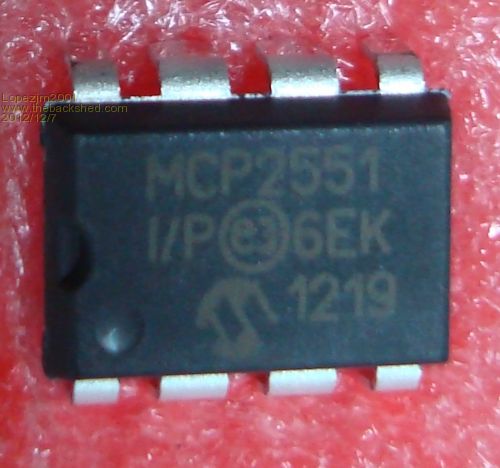
Ahh, sorry about that! Bad timing I guess. But as Mick pointed out the circuitry to add should be fairly straightforwar - so all is not lost. I'm sure John Lopez will let us know if that's true! If you do another rev of the ColorMax - how about exposing both CAN channels? Also, this chip from TI has better isolation than the MCP2551 : http://www.ti.com/product/iso1050. Isolation is an "interesting" characteristic for me because I'm hooking up to high voltage battery packs that have their own isolated ground separate from vehicle ground. And never the 'twain shall meet! However, I've sidestepped that issue for my project because I'm re-purposing the existing Denso device which one presumes already has such isolation in place. |
||||
| CircuitGizmos Guru Joined: 08/09/2011 Location: United StatesPosts: 1427 |
Yes, adding the circuits from the first page of this thread are not too much of a challenge. You can get a DIP MCP2551 and some TH resistors for a couple bucks and wire this CAN circuit into the ColorMax sea-of-holes. The CAN lines are on the Arduino footprint. I would have used machine-placed SMT and made the CAN circuit connections optional. Oh, well. As you say if another rev is done... Micromites and Maximites! - Beginning Maximite |
||||
| Lopezjm2001 Regular Member Joined: 08/07/2012 Location: AustraliaPosts: 42 |
Hi Gizmos, Geoff and JDH2550, I would like to set a standard (or let you guys set a standard or a concensus) for the CGcolormax1 as to which pins numbers to use for a CANport. At the moment I am going with pins 87 and 88. I know they conflict with D4 and D5. Any input or comments please? 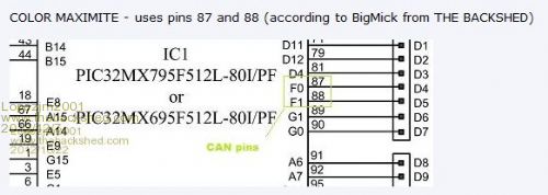
Lopez |
||||
| bigmik Guru Joined: 20/06/2011 Location: AustraliaPosts: 2981 |
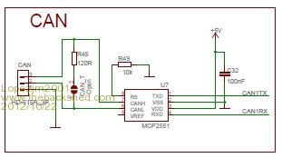
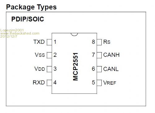
Hi Lopez, All, Firstly, CAN is not yet available on the Colour Maximite.. I think Geoff is going to include the routines using F0 and F1 as the CAN pins. Secondly, taking note of the section of my schematic, (the one with the pale yellow background), please note the pin Numbering of the IC is not the same as the PHYSICAL pin numbering so dont wire up as if the position of the pins are as shown, use the pinout as shown in the "package types" above., (i.e. The NUMBERS are correct, the physical location of the pins is not.) Also I have provided links to connect F0 to F1 as these are also used as D4 and D5 on the Arduino connector. This is so the CAN chip can be in circuit but not connected to the PIC32 unless you decide to use it. Regards, Mick Mick's uMite Stuff can be found >>> HERE (Kindly hosted by Dontronics) <<< |
||||
| Geoffg Guru Joined: 06/06/2011 Location: AustraliaPosts: 3363 |
Hi All, Yes, I plan to implement John Harding's CAN with the Rx signal on pin 87 of the 100 pin PIC32 (also Arduino D4) and Tx on pin 88 (Arduino D5). This is on the Colour Maximite so it should also work on Mick's board and the CGCOLORMAX1. CAN should also work on the Duinomite. This of course is subject to everything working out as planned, but I am confident it should be OK. I originally intended to put CAN into ver 4.1 but a number of bugs meant that I had to push 4.1 out early. So, now it will be in 4.2. Also, 4.2 will have support for RS485. I will probably put out a beta version first as I do not have the facilities for testing either CAN or RS485 and this should happen in early January. I hope that this helps, Geoff Geoff Graham - http://geoffg.net |
||||
| bigmik Guru Joined: 20/06/2011 Location: AustraliaPosts: 2981 |
Hi Geoff, Just curious, What support is added for RS485? The difference as far as I can see is the driver chips themselves. The TTL (or 3.3v TTL) interface should be the same as RS232 shouldn't it? Regards, Mick Mick's uMite Stuff can be found >>> HERE (Kindly hosted by Dontronics) <<< |
||||
| isochronic Guru Joined: 21/01/2012 Location: AustraliaPosts: 689 |
Just a thought - I see Microchip have updated the pic32 "Starter Kit II", it uses a pic32 '795L. Probably MM would run on it, with an adapter ? I think it includes CAN and USB etc. (edit) sorry this should probably be another thread. |
||||
| Page 1 of 5 |
|||||
| The Back Shed's forum code is written, and hosted, in Australia. | © JAQ Software 2026 |
