
|
|
Forum Index : Microcontroller and PC projects : Mini servo - Tower Pro SG90
| Page 1 of 2 |
|||||
| Author | Message | ||||
| paceman Guru Joined: 07/10/2011 Location: AustraliaPosts: 1329 |
Mini servos are usually used for control of models (planes, boats etc). I've been looking at one of these "Tower Pro SG90" (cost $4 from Deal Extreme, free postage) for a different job though i.e. to replace a small solenoid to release/lock a cat door! Solenoids are a lot more expensive, draw a fair bit of current (the whole time they're 'ON') and in the case of small solenoids they're not very powerful. The servos are geared DC motors and very small ones can produce a lot of torque. In the case of the SG90 (which is tiny) it can produce 2kg of torque and will hold it's position with very little current e.g. < 10mA. 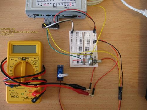
I've used this test setup to try different methods of controlling the servo using MMBasic V4.3 and the Maximite. 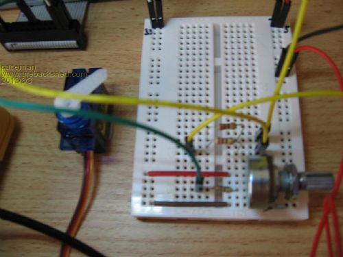
The test rig has the 3.3v MM supply connected across a 10K pot and the wiper voltage (green wire) is read on one of the analogue inputs (pin 5) via a 100 ohm resistor. That's scaled using MMBasic to give the correct pulse width for that position of the pot/servo. The servo connector has three leads, gnd, 5v, and it's pulse control lead connected to either a digital out pin or the PWM output, in both cases (yellow leads)via a 220 ohm resistor (more on that in the info below). The servo control is achieved by varying the pulse width between about 1-2 milliseconds and the pulses need to be maintained at about 50Hz (but the 50 is not critical). I've used the PULSE output command and the PWM command to do the control. Surprisingly (I thought) the PULSE control was much better and the PWM control was very jerky. The code is below (it's pretty simple  )and allows testing by either manual width input or input from the potentiometer (much better). I've included a lot of description for those unfamiliar with the servos. )and allows testing by either manual width input or input from the potentiometer (much better). I've included a lot of description for those unfamiliar with the servos.
Any comments gratefully received - and thanks again to TassyJim for his MM Edit program which makes life very easy! Greg ------------------ 'SERVO - Program to test the Micro Power SG90 servo motor using ' the original mono-colour Maximite and MMBasic V4.3 ' --------------------------------------------- 'Normal analogue servos hold position dependant on the incoming pulse width on 'the control lead. The pulse stream needs to be maintained to hold servo 'position and the normal pulse repitition rate is approx 50Hz but this is not 'critical over quite a wide range. 'The centre (neutral) posn'n for most servos is at a pulse width of approx. '1.5mS and the full pulse width range for most servos is approx 1mS to 2mS. 'The pulse width range needs calibrating for different servos so as to achieve 'their full movement range but not over-drive and thus possibly damage them. 'Pulse width Vs position is usually not fully linear, i.e. mid pulse width is 'not necessarily the centre servo position. Shorter pulses rotate the SG90 arm 'clockwise but this can be different for other servos. ' 'The SG90 has three leads: ' a) Gnd (usually brown) ' b) 5v supply (usually red - and usually the centre lead). This draws ' typically 50-80mA when moving and 5-10mA when holding or when ' there is no control pulse input. If over-driven the current can be ' above 200mA and damage may occur. Monitoring current on the servo ' lead is a good idea when testing! ' c) pulse control lead (usually yellow). ' 'Testing is conveniently done using a 10K linear pot connected across the 'Maximite's 3.3v supply and connecting the pot wiper to one of the Maximite 'analogue input pins via a 220 ohm resistor. Voltage at that pin can then be 'read by the program and scaled to provide the control pulses. The amplitude 'of the control pulses is not critical but should not exceed the 5v servo 'supply voltage. 3.3v pulses work well. 'The servo can be controlled with either the PULSE or PWM command. Control 'using PULSE requires the program to maintain the pulse stream, but is smooth 'and accurate. Control using PWM is simple and provides a continuous pulse 'stream in the program background till changed with another PWM command or 'stopped with a PWM STOP command. Unfortunately the pulse output seems to 'suffer 0.2mS pulse width steps, which is roughly 10% of the full servo range. 'Note that when using PWM control, the Maximite's PWM output circuit must have 'the voltage divider network removed to supply the full 3.3v pulse height. ' 'Rough SG90 pulse width Vs position calib'n using the PULSE command. ' Full range on the SG90 is: 2.4 mS (~90o) to 0.6mS (~270o) clockwise. ' 'When using the PWM command and the PWM output, the first argument is frequency ' and the second argument is a percentage of the period. At 50 Hz the ' period is 20mS thus e.g. 10% of that equates to a 2mS pulse. ' 'Rough SG90 PWM command Vs position calib'n when running at 50Hz (20mS period). ' Full range: 12.4% (~90o) to 3.2% (~270o) clockwise. ' PWM pulses run continuously in the program background ' ----------------------------------------------------- Initialise: SetTick 0,0: SetPin 11,0: SetPin 5,0: PWM STOP Print "Input type of servo control to use:" Print "1=Keybd_PULSE, 2=Keybd_PWM, 3=Pot_PULSE, 4=Pot_PWM" Input controltype On controltype GoTo Keybd_PULSE,Keybd_PWM,Pot_PULSE,Pot_PWM Keybd_PULSE: SetPin 11,8 'set pin 11 as digital out Pin(11)=0 'set pin 11 to 0 (in case it's at 1) Input "Input pulse width in mSecs: ",width 'range approx 0.6 to 2.4 mS SetTick 20,Pulseout 'set timer interrupt for pulse out every 20mS (50Hz) GOSUB Wait goto Keybd_PULSE Keybd_PWM: Input "Input pulse width in mSecs: ",width 'range approx 0.6 to 2.4 mS percent = width*5 'assuming frequency of 50Hz (i.e. 20mS period), thus %=width*100/20 PWM 50,percent 'start 50 Hz continuous pulse train GOSUB Wait goto Keybd_PWM Pot_PULSE: SetPin 11,8 'set pin 11 as digital out Pin(11)=0 'set pin 11 to 0 (in case it's at 1) SetPin 5,1 'set pin 5 as analog in SetTick 20,Pulseout 'interrupt for pulse out every 20mS (50Hz) Do volts = Pin(5) 'read wiper voltage at the pot position width = (0.5454*volts)+0.6 'from: slope=(2.4-0.6)/3.3 and y=Sx+c 'v$=Format$(volts,"V= %4.2f ") 'w$=Format$(width,"W= %4.2f") 'Print v$,w$ key$ = Inkey$ If key$ <> "" GOTO Initialise loop Pot_PWM: SetPin 5,1 'set pin 5 for analog input do volts = Pin(5) 'read wiper voltage at the pot position width = (0.5454*volts)+0.6 'from: slope=(2.4-0.6)/3.3 and y=Sx+c percent = width*5 'assuming frequency of 50Hz (i.e. 20mS period), thus %=width*100/20 PWM 50,percent 'start 50 Hz continuous pulse train 'v$=Format$(volts,"V= %4.2f ") 'w$=Format$(width,"W= %4.2f ") 'p$=Format$(percent,"Percent= %4.2f") 'Print v$,w$,p$ Pause 20 'seems to be needed, otherwise no pulse output key$ = Inkey$ If key$ <> "" GOTO Initialise loop Pulseout: Pulse 11,width IReturn Wait: key$ = Inkey$ If key$ = "" GOTO Wait 'wait for a keyboard press to input another pulse width return ------------------------- |
||||
| MicroBlocks Guru Joined: 12/05/2012 Location: ThailandPosts: 2209 |
Great! One of those things on my 'todo' list. This will be a great start. Thanks for figuring this out. Microblocks. Build with logic. |
||||
| Keith W. Senior Member Joined: 09/10/2011 Location: AustraliaPosts: 118 |
Hi paceman, Congratulations on operating the servo. I think that you are first to publish on using the Maximite with servos? Reading about your application I remembered a lock method that I have used. A car electric door lock actuator is an answer. These will give more than 25 mm of pin movement, only draws power when opening or closing and retain position when not powered. Their geared down motor method gives a long stroke with reasonable force, enough for a locking pin. To reverse the direction of travel the motor supply (12 Volts) is reversed. Usually only 1 of the 4 units in a car is a master unit with limit switches to turn off the supply at end of travel. I have included a borrowed photo and a link that leads to a description of another actuator sold by Jaycar (from whom I think that you must buy a kit of 4). A drawback could be the requirement for 12 Volts at maybe an amp of current, I cannot remember but as the little motor is geared down it may require less. A good source would be a car wrecker. Keith W. http://www.jaycar.com.au/images_uploaded/powrlock.pdf 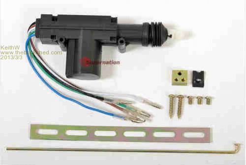
|
||||
| paceman Guru Joined: 07/10/2011 Location: AustraliaPosts: 1329 |
This section of comments in the program needs editing (it's correct in the description given in the post). The wiper is connected to the analogue input pin via a 100 ohm resistor - not 200 as shown above from the program listing. Also, the paragraph quoted above should have the following sentence at the end. "The servo pulses from either the PWM output or the digital PULSE output pins are connected to the (yellow) servo control lead via 220 ohm resistors." Greg |
||||
| paceman Guru Joined: 07/10/2011 Location: AustraliaPosts: 1329 |
Hi Keith, Thanks for that - I surprised myself! I knew nothing about them until a few days ago. Most of the information, except program which is all mine  came from the Polulu site, Servo Primer came from the Polulu site, Servo Primer
About the car electric door actuator - they're a good option but too big for my project and as you said, they need 12v, the same as the little solenoids do. The servo running off 5v is handy. I remember seeing one of those being used on U-Tube operating a 90o water hose valve. The bloke that did it had trouble with tom-cats smelling up his yard so he rigged up an IR beam at cat level that triggered the servo when the cat walked through the beam - immediate high pressure hosing  To make it more interesting he also pre-triggered a video camera (another beam?) for a few seconds and posted the action. He also got to find out who the culprits were. The video's probably still there somewhere. To make it more interesting he also pre-triggered a video camera (another beam?) for a few seconds and posted the action. He also got to find out who the culprits were. The video's probably still there somewhere.
(BTW, I actually like cats generally). Greg |
||||
| davematt Regular Member Joined: 27/09/2011 Location: AustraliaPosts: 55 |
Hi Greg, I have had some success using a servo for an infra red rat trap. You may want to look at a picaxe chip, the M 08 is much cheaper than a MM, and the code very similar. Its PWM output is quite stable enough, the pulse command has the exact problem you mentioned. I believe the traditional solution is to use an interrupt, but haven't tried it. Another advantage is the 5 volt operation, your servo is hoping for at least 4.8 volts from 4 nicads, but recent models go better on 6 volts. As above, congratulations on a very thorough treatment. David |
||||
| paceman Guru Joined: 07/10/2011 Location: AustraliaPosts: 1329 |
Thanks Dave. The picaxe is probably a good option except I want to do other things at the same time, i.e. read an RFID and control a display, so the Maximite makes all that very possible - and not too much more expensive (for a one-off anyway). I'd love to see a video of your picaxe system catching rats! Makes me wonder whether the world beat a path to your door (...a better mousetrap etc)! It's interesting that you say the picaxe PWM output is quite stable - stability isn't so much the issue with the Maximite PWM, it's more the ~ 10% pulse width jumps which doesn't happen with the PULSE command which is smooth. You do see the period of the PWM pulse moving around a bit with the oscilloscope but that's not supposed to matter since it's the pulse width that matters. It's a bit of a pity because PWM runs in the background whereas PULSE has to use the software TIMER interrupt facility of MMBasic. The timer interrupt gives a very stable period output(again seen with the 'scope) and still presumably leaves plenty of time for the main program, but that stable period is not supposed to matter. Geoff's MMBasic documentation for the PULSE command says: Notes: For a pulse of less than 3 mS the accuracy is � 1 μS. For a pulse of 3 mS or more the accuracy is � 0.5 mS. A pulse of 3 mS or more will run in the background. Geoff may have had to compromise and only enable background output above 3mS for PULSE, but it does have the width accuracy below 3mS which is great. That change of spec above 3 mS (just higher than any normal servo pulse width), to coarser width control and to background output, was probably quite deliberate to enable good servo control without compromising something else in MMBasic. Geoff's PWM command documentation says: The frequency of the output is locked to the PIC32 crystal and is very accurate and for frequencies below 100 KHz the duty cycle will be accurate to 0.1%. This seems a bit odd because 0.1% of the 50Hz, i.e. 20mS period is 0.02mS which would be very fine control similar to the PULSE command below 3mS. That doesn't line up with the 'jumps' I see in the output which are about 10% of the period and there's nothing else going on in the program. This is a bit of a pity because the PWM command is easy to use, happens in the background, presumably at all pulse-widths and doesn't take up any other pin outputs. The other strange thing is the PAUSE 20 (mS) command needed to allow the PWM output to start. Anything less than 20 and no pulses were generated at all (watching on the 'scope). Maybe Geoff could comment on this. Greg |
||||
Bill.b Senior Member Joined: 25/06/2011 Location: AustraliaPosts: 245 |
The picaxe has a 'SERO - servopos' command that takes care of the pulse requirements you only have to give it a number between 75 and 225 to set the servo to the required position. I have a catipila with 8 of the miniature servos powered by a picaxe 20x2. The grandchildren love watching it move. Bill In the interests of the environment, this post has been constructed entirely from recycled electrons. |
||||
| paceman Guru Joined: 07/10/2011 Location: AustraliaPosts: 1329 |
I guess a lot of people use picaxe for servos - also Arduinos. I've noticed the Arduino havs a 'MAP' command too (written in 'C') for servos that automatically scales user input parameter limits to the servo pulse width/position limits. It's not that difficult to get around with MMBasic though. |
||||
| Geoffg Guru Joined: 06/06/2011 Location: AustraliaPosts: 3363 |
That is strange. The PWM output is generated by a dedicated peripheral in the PIC32 which has nothing to do except count down the various counters to generate the output. Any jitter should be less than 50 nanoseconds. I just tested it on the CMM and it is stable as a rock. So stable that I cannot measure any jitter! I presume that you don't have any audio filters or attenuators on the output? Are you using the PWM command? What else? Something in your setup must be wrong. The PAUSE command has nothing to do with the PWM command. Geoff Geoff Graham - http://geoffg.net |
||||
| paceman Guru Joined: 07/10/2011 Location: AustraliaPosts: 1329 |
Hi Geoff - thanks for the reply, The full code is in the first post of this thread but the relevant bits are below: ---------------------------- Initialise:
SetTick 0,0: SetPin 11,0: SetPin 5,0: PWM STOP Print "Input type of servo control to use:" Print "1=Keybd_PULSE, 2=Keybd_PWM, 3=Pot_PULSE, 4=Pot_PWM" Input controltype On controltype GoTo Keybd_PULSE,Keybd_PWM,Pot_PULSE,Pot_PWM . . . Pot_PULSE: SetPin 11,8 'set pin 11 as digital out Pin(11)=0 'set pin 11 to 0 (in case it's at 1) SetPin 5,1 'set pin 5 as analog in SetTick 20,Pulseout 'interrupt for pulse out every 20mS (50Hz) Do volts = Pin(5) 'read wiper voltage at the pot position width = (0.5454*volts)+0.6 'from: slope=(2.4-0.6)/3.3 and y=Sx+c 'v$=Format$(volts,"V= %4.2f ") 'w$=Format$(width,"W= %4.2f") 'Print v$,w$ key$ = Inkey$ If key$ <> "" GOTO Initialise loop Pot_PWM: SetPin 5,1 'set pin 5 for analog input do volts = Pin(5) 'read wiper voltage at the pot position width = (0.5454*volts)+0.6 'from: slope=(2.4-0.6)/3.3 and y=Sx+c percent = width*5 'assuming frequency of 50Hz (i.e. 20mS period), thus %=width*100/20 PWM 50,percent 'start 50 Hz continuous pulse train 'v$=Format$(volts,"V= %4.2f ") 'w$=Format$(width,"W= %4.2f ") 'p$=Format$(percent,"Percent= %4.2f") 'Print v$,w$,p$ Pause 20 'seems to be needed, otherwise no pulse output key$ = Inkey$ If key$ <> "" GOTO Initialise loop Pulseout: Pulse 11,width IReturn Wait: key$ = Inkey$ If key$ = "" GOTO Wait 'wait for a keyboard press to input another pulse width return --------------------------------------- I've removed the voltage divider in the PWM output as per your discussion under "Sound Output" in the March 2011 SC issue. The 1K to ground is now disconnected, the 5.6K is replaced with a link and I can see the full 3.3v pulses on the scope from both the PWM and I/O pin 11 that I'm using for the PWM and PULSE control cases respectively. I've also got just a 220 ohm resistor in series with each output to the servo control wire and I plug/unplug each depending on which control method I'm using. For both the PULSE and PWM control cases I'm using a nominal 50HZ period. Using PULSE control and the TIMER interrupt the pulses are rock steady on the 'scope and widen smoothly as the pot is rotated. With PWM control the period of the pulses jumps around a bit (typically between about 18-22 mS period) and jumps around a bit more (typically between about 16-24 mS period) if the extra print statements etc are being used, i.e. not commented out as they are above. The pulse width is still constant for a given pot position but as the pot is gradually turned the pulse width doesn't widen (or narrow) with it smoothly but jumps in about 0.2 mS jumps - this is seen on the 'scope and in the servo positioning. From what I've read Servo Primer the variable period apparently shouldn't matter - and doesn't seem to, because if the pot is not moved the pulse width is constant and so is the servo position, even though the period is jumping around by a few mS. I don't know why the PAUSE is needed but certainly with the above code, if it isn't there the PWM output pulses don't start. I tried shorter pauses but 20 is needed. Many thanks for your help. Greg |
||||
| Geoffg Guru Joined: 06/06/2011 Location: AustraliaPosts: 3363 |
Sorry Greg but this is one of the "cannot see the woods for the trees" things. Your lengthy code obscures the problem. You need to have just a few lines to demonstrate a problem. For example, I used: PWM 50, 25, 25 in the test and it was perfect. So, what is causing your problem? One answer might be that (according to my quick read) you have the PWM command in a loop where you are constantly re-issuing PWM commands - this would certainly cause jitter as the registers are constantly being reset to zero. There could be other issues but reverse engineering your code is difficult. Try reducing the problem to just a few lines of code. I bet that the problem will then go away. Then the issue will be to find exactly what additional feature of your code is causing the jitter. Geoff Geoff Graham - http://geoffg.net |
||||
| paceman Guru Joined: 07/10/2011 Location: AustraliaPosts: 1329 |
Hi Geoff, I've been fiddling with this for a couple of hours but you're dead right, it's better to simplify things. I,m using my original Maximite, so only two PWM arguments. If I put in only the PWM command, straight from the keyboard and have the 'scope measuring the pulse width I get: PWM arg's Width (mS)
50,6 1.2 50,6.5 1.4 50,7 1.4 50,7.5 1.6 50,8 1.6 50,8.5 1.8 50,9 1.8 50,9.5 2.0 50,10 2.0 The period in rock steady but as you see the pulse width jumps in 0.2mS increments. The PAUSE thing is another issue but I'll try to find out what's happening here first. Greg |
||||
| Keith W. Senior Member Joined: 09/10/2011 Location: AustraliaPosts: 118 |
Hi Greg, Perhaps you are expecting a little much of the PWM output; you require a PULSE rather than PWM. You require a pulse that varies between 1 and 2 milliseconds at a repetition rate of about 50 Hz to control the servo. Requiring this from the PWM has found you requiring small numbers for width. Using the PWM directly requires a 50 HZ pulse of 5% width to achieve a 1 millisecond servo pulse. With a stated PWM resolution of 0.1% overall you are limited to 2% resolution at this width and perhaps you have found that you do not achieve this in practice. The lowest frequency for the PWM output is 20Hz. Perhaps near this rate it does not have the 0.1% accuracy for width? Hopefully Geoff will comment on my risky supposition. A better solution may be to use the PWM output as a 50 HZ generator with maybe 50% duty cycle and wired back to an input pin. This pin programmed to perform an interrupt on an input edge. The interrupt routine programmed to initiate a PULSE on an output pin of the required width for the servo. Alternatively you could use the SETTICK command to trigger the interrupt. (SetTick 20, DoPulse and easily stopped by SetTick 0,0 ) Once started the PWM output (or Tick) and thereby the Pulse output can run fairly independent of the rest of the program. The 1 to 2 milliseconds pulse width can be set by a variable used by the interrupt routine and altered by the control program to an accuracy of +- 1 Microseconds according to the Manual, ie 1 part in 1000. Any �jitter� in the repetition rate of the pulse caused by interrupt response time should not affect the servo. Keith W. |
||||
| Bill.b Senior Member Joined: 25/06/2011 Location: AustraliaPosts: 245 |
Hi all This sample program will operate a servo over its full range using pulse output. The frequency and pulse duration is as stated by Keith. [code] ' Servo commands. frequency = 50 Hz pule width is 0.5ms to 2.5ms for full operation. ' this is a test for a analogue servo. which will rotate from one end to the other. ' this rotate in 400 ms steps. then rotate to the centre position. SetPin 15,8 main: For a = 1 To 35 Pulse 15,0.5 Pause 20 Next a Pause 1000 For a = 1 To 35 Pulse 15,2.5 Pause 20 Next a Pause 1000 For b = 2.5 To 0.5 Step -0.1 For a= 1 To 35 Pulse 15,b Pause 20 Next a Pause 400 Next b Pause 1000 For a = 1 To 35 Pulse 15,1.3 Pause 20 Next a Pause 1000 GoTo main [/code] Bill In the interests of the environment, this post has been constructed entirely from recycled electrons. |
||||
| paceman Guru Joined: 07/10/2011 Location: AustraliaPosts: 1329 |
The 10% I quoted above is wrong; the pulse-width jumps using PWM are just 1% which equates to the 0.2mS jumps in pulse width shown in the 2:17pm post - this is all at 50Hz i.e. a period of 20mS. There is no jitter at all in the period when successive single PWM commands are issued with increasing 'duty cycle %', i.e.the second argument. However the 1% (i.e. 0.2mS) jumps in pulse width with successive single commands, can be seen in the 2:17pm post. The MMBasic manual quotes: at frequencies below 100 KHz the duty cycle will be accurate to 0.1% but it appears that the accuracy is 1%. Accuracy of 0.1% is good for the servo control but 1% is too coarse (at 50Hz). Hi Keith, I've noted a couple of times in the thread that jitter in the pulse repetition rate doesn't matter, it's the pulse width that matters. I have used the SETTICK interrupt with the PULSE command (see earlier post) and it works very well. Using PWM as a 50Hz generator and wiring it back to give a hardware interrupt to trigger a PULSE command also sounds like another good option - I hadn't thought of that one; I'll give that a go too. The original point of the thread was to give two options i.e. using the PULSE command or the PWM command, with some code, to easily test the servo and calibrate its range. PULSE combined with SETTICK works very well, but PWM which would be the easiest to use seems to either have an accuracy problem, or maybe the Manual specs for PWM are wrong, or quite possibly I'm doing something wrong. I can already use the servo effectively for my project but I'd like to clear it up mainly because I thought some routines to test servos would be useful for the library. It might also inspire using the Maximite and MMBasic in a further direction, i.e. servo control. Greg |
||||
| Keith W. Senior Member Joined: 09/10/2011 Location: AustraliaPosts: 118 |
Hi Greg, I apologize for not reading your code properly; you had already embraced using SETTICK. I was caught up in your troubles with PWM. But that has helped me to understand some limitations of different methods. As everybody seems to be coming clean can I claim that it was a senior�s moment, being 69 years and living in Ringwood (Vic). Keith W.  |
||||
| paceman Guru Joined: 07/10/2011 Location: AustraliaPosts: 1329 |
No need for apologies Keith, I appreciate your interest. I just tried your idea of using PWM as a 50Hz generator, feeding it back to a digital input set up for a leading edge interrupt trigger and outputting with the PULSE command from the interrupt routine. It works beautifully. I scale the pulse width from the pot wiper analogue-in as before and the calculated width is passed to the PULSE command - simple. I've also put a 10K resistor in series from the PWM out, to the digital in for protection - not sure that it's at all necessary. ----------------------------- Start:
SetPin 5,1 'analogue in setpin 11,8 'digital out pwm 50,20 'start "pulse generator" for triggering setpin 14,6,pulse_out 'L > H interrupt do volts = pin(5) width = (0.545*volts)+0.6 'from calib'n and 20mS period (50Hz) percent = width*5 'assuming 20mS period key$ = Inkey$ If key$ <> "" GOTO stop loop pulse_out: PULSE 11,width ireturn stop: SetPin 5,0 setpin 11,0 pwm stop setpin 14,0 end ------------------------------ |
||||
| paceman Guru Joined: 07/10/2011 Location: AustraliaPosts: 1329 |
Geoff, When you tested the PWM output did you try successive single PWM commands with small width increments to see if the 1% (0.2mS at 50Hz) "step" exists in pulse-width output on your system? I'm interested because if it does I'll drop the direct PWM option for the servo test options and go with the "PULSE/SETTICK" option and the "PWM as pulse generator wired to an interrupt input pin to trigger pulses" option. Both these options work well; the first one though uses up the SETTICK command, and the second one uses an extra pin for the hardware interrupt input. People then have the choice of which compromise is best for them. Greg |
||||
| MicroBlocks Guru Joined: 12/05/2012 Location: ThailandPosts: 2209 |
I think using an input pin as an interrupt would not accomplish much more then just using the settick command. They are both interrupts and not using the PWM keeps it available for other purposes (sound). I think the settick would actually be more accurate. With a scope that is easily checked and tested. Microblocks. Build with logic. |
||||
| Page 1 of 2 |
|||||
| The Back Shed's forum code is written, and hosted, in Australia. | © JAQ Software 2026 |
