
|
|
Forum Index : Microcontroller and PC projects : Maximite printer interface
| Author | Message | ||||
CircuitGizmos Guru Joined: 08/09/2011 Location: United StatesPosts: 1427 |
I was cleaning out my work area and up on one of the shelves was a Panasonic printer. So just for fun, I made a printer interface for the CGCOLORMAX2. Wiring only took a few minutes, as did writing the code. Here is the hardware: 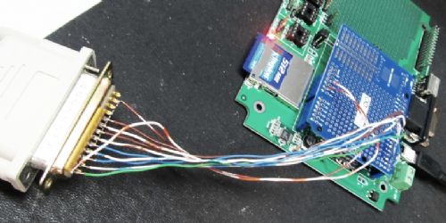
Here is the prntfile.bas code: printerinit IF MM.CMDLINE$ = "" THEN INPUT "Filename: ",filename$ ELSE filename$ = MM.CMDLINE$ ENDIF OPEN filename$ For input As #1 ' Read the file DO printchar(INPUT$( 1, #1 )) LOOP UNTIL EOF(#1) CLOSE #1 SUB printchar(character$) PORT(21, 8) = ASC(character$) PIN(29) = 0 PAUSE(50) PIN(29) = 1 PAUSE(50) END SUB SUB printerinit SETPIN 21, 9 SETPIN 22, 9 SETPIN 23, 9 SETPIN 24, 9 SETPIN 25, 9 SETPIN 26, 9 SETPIN 27, 9 SETPIN 28, 9 SETPIN 29, 9 PORT(21, 8) = 0 PIN(29) = 1 END SUB Here is the text file: Hello World! This is a printer test. CircuitGizmos Here is the result: 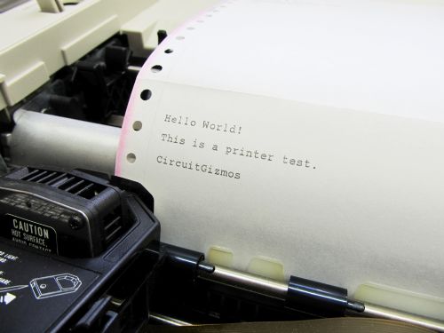
Ah, to hear dot-matrix again! Micromites and Maximites! - Beginning Maximite |
||||
Grogster Admin Group Joined: 31/12/2012 Location: New ZealandPosts: 9986 |
Excellent stuff, CG!!!!  
I was wanting to add a printer interface to my latest security system idea(as well as logging to the SD card), so might have to steal this... I will do some tests, but as it seems so easy to get it working, it is a strong possibility that it will be included in the code. Naturally, you will be credited in the code should I do this. Dot-matrix printers still have their uses. Smoke makes things work. When the smoke gets out, it stops! |
||||
| CircuitGizmos Guru Joined: 08/09/2011 Location: United StatesPosts: 1427 |
Thanks, Grogster! Micromites and Maximites! - Beginning Maximite |
||||
djuqa Guru Joined: 23/11/2011 Location: AustraliaPosts: 447 |
Still are a few Dotmatrix printers being made and sold with centronic interfaces So great on making the maximite printer interface/code VK4MU MicroController Units |
||||
| Grogster Admin Group Joined: 31/12/2012 Location: New ZealandPosts: 9986 |
Can you please post the circuit? I see you have a yellow thing soldered to the LPT plug - I am guessing this is a resistor network in the area of 10k or so as pull-ups on the data lines? Smoke makes things work. When the smoke gets out, it stops! |
||||
| MOBI Guru Joined: 02/12/2012 Location: AustraliaPosts: 819 |
If any one is interested, I did up an i2c module (picF88) that outputs an 8 bit ascii byte with a strobe pin - runs with dot matrix parallel printers. David M. |
||||
bigmik Guru Joined: 20/06/2011 Location: AustraliaPosts: 2981 |
Hi Rob, Just curious, Why did you use Open Collector outputs? If you set as digital outputs (x,8) you may be able to do away with the Resistor pack... Or is it to do with the +5V printer input and the respack is pulled to +5V to provide a solid High? I suspect this is the case. I think +5 is present on pin 36 of the centronics plug anyway... Good work Rob, Regards, Mick Mick's uMite Stuff can be found >>> HERE (Kindly hosted by Dontronics) <<< |
||||
| CircuitGizmos Guru Joined: 08/09/2011 Location: United StatesPosts: 1427 |
Yes. That is a 10k resistor pack. Pulls pins 1-9 on the 25-pin connector up to 5V. Pin 1 is the printer data valid line - when pulsed low the printer accepts the ASCII data value on pins 2-9. I used 5V logic to be sure that it would work with this printer. Centronics +5V isn't supposed to be used for anything, according to the printer manual. This is just an example "how-to" I did mainly because I had the printer. I'm not defining any particular pins as Maximite printer interface pins. The printer interface has more than just the 8 data and one signal line - I made this as minimum as possible. There is, for instance, a 'ready' line that would be used to let the Maximite know that the printer is ready for more data. Micromites and Maximites! - Beginning Maximite |
||||
| The Back Shed's forum code is written, and hosted, in Australia. | © JAQ Software 2026 |
