
|
|
Forum Index : Microcontroller and PC projects : I2C Interface Question
| Author | Message | ||||
| Zonker Guru Joined: 18/08/2012 Location: United StatesPosts: 761 |
Ok Gent's... An update is in order... It turns out that there seems to be an open trace on the colourMAX board. I was using the A4-A5 pins on the shield connector and found the D13 signal open. D12 is ok. So, I moved the wires to the main connector instead. Now I am getting the correct MM.I2C status of 0. I tried collecting data and sometimes get a number or two... I think that mostly the data should be reading as zeros as the IC has not collected any "run-time" and stored it in the time counters. It has a memory area and I will try to store data there. The next question is how to transmit a "NAK" response after reading the last byte from the IC... I see that you can send a number of data bytes ahead of the read-back data as described in the manual, but I don't think that helps here... I'll keep hackin at it... Thanks for all the help Guy's..!! 
Edit: Perhaps a poke around the I2C library would be good thing...! |
||||
CircuitGizmos Guru Joined: 08/09/2011 Location: United StatesPosts: 1421 |
A CircuitGizmos ColorMax? (CGCOLORMAX1 or CGCOLORMAX2)? Did you set J14 and J15? Micromites and Maximites! - Beginning Maximite |
||||
| MOBI Guru Joined: 02/12/2012 Location: AustraliaPosts: 819 |
I use the Circuitgizmo's CGCOLORMAX1 with I2C sda on the sea of holes I/o socket 12 (pin6) and scl socket 13 (pin 8). Ov and +5 (3.3) self explanatory. The setup works with external pullups fitted or not. Are you using the MM I2C commands correctly? I haven't checked the device you are using but is it a 7 bit address or 10bit? David M. |
||||
| Zonker Guru Joined: 18/08/2012 Location: United StatesPosts: 761 |
Hey Giz.. ! You bet... I actually have both of them... The CM-1 has the open, and yes I got the J-14, J-15 jumps in place. I tried confirming with a simple LED pull to GND test. No big deal though... I just rewired the IC back to the main connector and I think it's got data now... I'll try hooking up the sniffer and try learning a few I2C commands. I think part of the problem is "newbie" related and I need some time studying some example code... I'm trying to create a hand held Demo version of the EIS to maybe show at an upcoming meeting, so I needed 2 CMM's to work with. I got most of the hardware fitted but this is the first I2C chip goin on... Your boards make a grate working prototype base for the project and I almost filled up the sea of holes area... I'm well pleased with them.. |
||||
| Zonker Guru Joined: 18/08/2012 Location: United StatesPosts: 761 |
Yea MOBI I got the PDF posted at the top.. It's a 7bit as described, and... Yes I'm a total nubie when it comes to the MM way of typing in the right command codes... I was going to look around at some example code for a while, and try again... Thanks for any Guru I2C advice on trying to generate the right read sequence...!! |
||||
| MOBI Guru Joined: 02/12/2012 Location: AustraliaPosts: 819 |
Here's a pic of my set up. 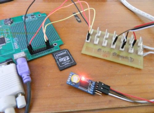
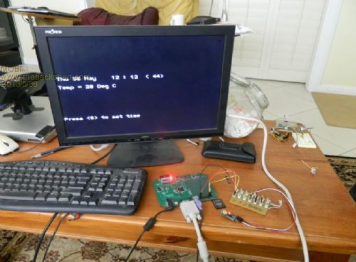
David M. |
||||
| MOBI Guru Joined: 02/12/2012 Location: AustraliaPosts: 819 |
@zonker can you send an example of the MM i2c read/write code you are using. Meanwhile, I'll have a look at the data sheet of the device you mentioned at the beginning of the thread. David M. |
||||
| Zonker Guru Joined: 18/08/2012 Location: United StatesPosts: 761 |
Was trying to get started with this: Dim icdat(30) I2CEN 100, 1000 I2CRCV &H6B, 0, 21, icdat(0) I2CDIS Print ">"; For p=0 To 21 Print icdat(p); Next p Print" <" Print "stat:" MM.I2C I think if I store some data in the memory area of the IC, I can have some constant data to read back... Thanks for your help David...!! |
||||
| MOBI Guru Joined: 02/12/2012 Location: AustraliaPosts: 819 |
@zonker That code looks like it should work but it would be a good idea to set your register pointer to say zero or the register you want to read/write first. The device will read from wherever the pointer was set previously. Also, there might be control register bits that may be inhibiting your actions. the code: i2crcv &H6b,1,21,icdat(0),1,0 should set up the pointer to register 0 and then read all registers from 0 to 20. the ,1,0 on the end of the command writes 1 byte of 0 to the device first which sets the register pointer to 0. I've got to go out for a couple of hours but will check on progress when I get home. David M. |
||||
| CircuitGizmos Guru Joined: 08/09/2011 Location: United StatesPosts: 1421 |
@Zonker: I know you moved things around anyway, so it doesn't matter, but J14 and J15 jumpers are in different positions for CGCOLORMAX1 and CGCOLORMAX2. If I'd known you were going to run out of holes, I could have put a few more in the box for free. That sometimes causes other parts to be lost, though.  
Thanks for the nice feedback! Micromites and Maximites! - Beginning Maximite |
||||
| MOBI Guru Joined: 02/12/2012 Location: AustraliaPosts: 819 |
@Zonker I tried a couple of RTC I2C devices with and without the 4k7 pull ups on the SDA and SCL lines. Only one worked without the pull ups but both worked with them. Have you got pull ups on your lines? @CG and /or Geoff, has any thought been given to the situation where PS2 keyboards are no longer available? David M. |
||||
| Zonker Guru Joined: 18/08/2012 Location: United StatesPosts: 761 |
Good evening Dave Humm.. I just happen to see a couple of 8.2k resistors that were easy to get , so I attached them to the 3.3v line. The PDF says anything 2.5 to 5v on the comm's should be ok. I have herd of anywhere from 4.7 to 10k used as the pull-ups, so I didn't think it was a big deal... I could replace them for the 4.7k pulls if you think it's a good thing... distance for the wires is about 1 to 2 inches... Sorry for the late start tonight... (didn't get much time) Zonk |
||||
jman Guru Joined: 12/06/2011 Location: New ZealandPosts: 711 |
I would connect the pull ups to 5V (the I2C pins are 5V tolerant) Jman |
||||
| MOBI Guru Joined: 02/12/2012 Location: AustraliaPosts: 819 |
The 8k2 resistors are fine. Anything from say 2K to 10K is ok. The higher you go in data speed, the lower the pull-up resistance values needs to be. As for lead length, I've got away with a couple of feet without hang-ups. Depends how clean you power supply is. I don't like switch mode PS on Maxi Mite - personally, I think they are too noisy. Just arrived home from a 400odd kilometre drive from Adelaide (capital of South Australia). We don't have quite as many states as you guys and we manage quite nicely to stuff up what we have. 
David M. |
||||
| Zonker Guru Joined: 18/08/2012 Location: United StatesPosts: 761 |
Just took a quick check this morning after adding the code change to properly adjust the address pointer. The read back data looks stable with the values in the same bytes every time. Got to get off to work now, but will try writing to the memory area when I get back... Everything seems to be working ..!! Thanks for all the help Gent's !!  |
||||
| MOBI Guru Joined: 02/12/2012 Location: AustraliaPosts: 819 |
So would I, but if the device operates at 3.3 volts its not a problem unless you have older devices that are +5v only. It is good to see someone using I2C - IMO it is not used enough. Seems to be some sort of mystique to it?? David M. |
||||
| vasi Guru Joined: 23/03/2007 Location: RomaniaPosts: 1697 |
Just tested to see if BBCode parser will parse the square brackets inside code tags ... in the preview looks good. [code] [link=your_link_here]your_description_text_for_your_link[/link] [/code] Now, replace link and /link with url and /url inside squared brackets... Glenn, can you "help" the BBCode parser to skip code content? Hobbit name: Togo Toadfoot of Frogmorton Elvish name: Mablung Miriel Beyound Arduino Lang |
||||
