
|
|
Forum Index : Microcontroller and PC projects : Right Shifting VGA screen
| Author | Message | ||||
bigmik Guru Joined: 20/06/2011 Location: AustraliaPosts: 2870 |
Hi Lads/Lasses, After discussing with Geoff about a desire (of mine) to move the VGA text approximately 1 character to the Right I think we have come up with a workable solution. I can repeat it all here again but full details are included here in this PDF I have quickly knocked up. 2013-06-05_022155_Right_Shift_of_CMM_text.pdf The end result is, based on tests with my 8" VGA screen, that 80 column text is now moved approximately 1 full character to the right which enables the full screen to be visible on the VGA monitor. In Mode 4 the result is even better as the Text seems to move so that the full screen is more or less fully centralised. Anyway I am interested in hearing feedback or improvements to this design. Regards, Mick Mick's uMite Stuff can be found >>> HERE (Kindly hosted by Dontronics) <<< |
||||
| robert.rozee Guru Joined: 31/12/2012 Location: New ZealandPosts: 2292 |
if you tied the bottom end of the capacitor to an IO pin that was capable of being tristated, then it may be possible, under program control, to switch the shifting effect on and off. this could be expanded upon to allow for a custom shift for each of the different video modes. |
||||
| bigmik Guru Joined: 20/06/2011 Location: AustraliaPosts: 2870 |
Hi Robert, That should work just as well, although the real problem I see is that the effect is about 1 character width in 80 column mode and maybe 1 (wider) character in mode 4 (about twice the actual 80 column mode shift)... If you increase the delay the effect is ineffective and the whole screen is upset and blurred out... What would be best is if the effect of the `hardware' delay could somehow be implemented in the C source but Geoff assures me that this would be quite a difficult feat and if HE thinks it would be difficult I would have NO chance at all. Regards, Mick Mick's uMite Stuff can be found >>> HERE (Kindly hosted by Dontronics) <<< |
||||
| Juri74 Senior Member Joined: 06/02/2012 Location: ItalyPosts: 162 |
Hello Mick, that's a great work! i've that problem on my GBS8200, now it's fixed! thank you again! Juri |
||||
| MicroBlocks Guru Joined: 12/05/2012 Location: ThailandPosts: 2209 |
What would the delay time be with those values? If you heat the R and C or cool them does it change enough to scramble the picture? if the time is short enough it might be doable with some gates or a counter ic. It might also allow for a different delay for each mode. Microblocks. Build with logic. |
||||
| bigmik Guru Joined: 20/06/2011 Location: AustraliaPosts: 2870 |
Hi Juri, I am glad it fixed your problem, but I am a little confused... I searched GBS8200 and it is a EGA/CGA/YUV to VGA converter. And it has position adjustments as well... I must be missing something.. Is your GBS8200 a VGA to Composite converter? Regards, Mick Mick's uMite Stuff can be found >>> HERE (Kindly hosted by Dontronics) <<< |
||||
| bigmik Guru Joined: 20/06/2011 Location: AustraliaPosts: 2870 |
Hi Tz, My original idea was to do the delay through a gate/series of gates but I calculated that 1 character delay was 5.6uS and most of the gates I looked at were in the nS range for Propagation delays... Then I requested the source code so that I could `play around' and maybe add a simple delay here or there and shift things.. Geoff helped me to compile the code to a HEX file and kindly gave me some pointers of where to look at in the code but also said it wasn't going to be easy... Then he mentioned this method which I tried and it worked. OK as for delay, if my calc of 5.6uS is accurate the delay would be around 5uS as I feel it is just under 1 character shift. As for heat and cold ... I cant answer that yet. Heat and cold so far have had no affect for me but you could always change the CAP or resistor down a value or two to reduce the delay and minimise any possible impact of heat/cold. I didn't push it to the nth degree but I can tell you that a 1k Resistor causes the loss of sync problem so its max must be between 680R and 1k (or 5 to 7.5uS) Regards, Mick Mick's uMite Stuff can be found >>> HERE (Kindly hosted by Dontronics) <<< |
||||
James_From_Canb Senior Member Joined: 19/06/2011 Location: AustraliaPosts: 265 |
Would it be worthwhile using one of those small blue variable resistors? That way you could adjust the resistance for different modes and you could adjust to the resistance that gives the best result - which may not be available as a fixed resistor value. The downside is that they're bigger than a resistor and harder to fit onto a tight circuit board. James My mind is aglow with whirling, transient nodes of thought careening through a cosmic vapor of invention. Hedley Lamarr, Blazing Saddles (1974) |
||||
| bigmik Guru Joined: 20/06/2011 Location: AustraliaPosts: 2870 |
Hi James, Of course that would work as well... But I wasnt interested in pushing it anymore than I needed.. (well after I realised that I was near the max I could push it anyway) I have then posted my findings for all to see/praise/criticise (cross out what doesn't apply). 
Regards, Mick Mick's uMite Stuff can be found >>> HERE (Kindly hosted by Dontronics) <<< |
||||
vegipete Guru Joined: 29/01/2013 Location: CanadaPosts: 1084 |
Just mumbling out loud here, but what does the delayed pulse look like? Does a slow rise time result in the different SPI channels triggering differently and hence the loss of sync? Could a gate or transistor sharpen the edge to give cleaner signals? Visit Vegipete's *Mite Library for cool programs. |
||||
| bigmik Guru Joined: 20/06/2011 Location: AustraliaPosts: 2870 |
Hi Pete, I havent `scoped' the signal.. but it would put a parabolic curved slope on the leading and falling edges Similar to this cct 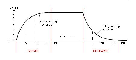
A gate would sharpen the pulse of course BUT as the SPI input triggers are tied tied together and they are in the same chunk of silicon you can assume that they will all trigger at exactly the same level.. The proof is that the signals still appear to be pixel perfect in alignment on my screen in 80 column and mode 4 (40col??) modes. Maybe other will have a different experience than me.. Time will tell I suppose The bottom line is I am happy that it works, it just steals back a small bit of my lost display area and makes my small 8" (non-adjustable) screen very usable . Regards, Mick Mick's uMite Stuff can be found >>> HERE (Kindly hosted by Dontronics) <<< |
||||
| robert.rozee Guru Joined: 31/12/2012 Location: New ZealandPosts: 2292 |
that might be a big hope, i'd certainly not be betting any money on it. in any production solution i'd certainly be adding in a schmitt trigger to ensure a sharp edge. a NC7WZ17 would do the trick nicely, smd in a 6-pin package, part of the 'TinyLogic' family. |
||||
| Geoffg Guru Joined: 06/06/2011 Location: AustraliaPosts: 3165 |
The inputs that we are talking about already have schmitt trigger circuits on the PIC32 silicon. In fact most PIC32 inputs use schmitt trigger circuits. Geoff Graham - http://geoffg.net |
||||
| robert.rozee Guru Joined: 31/12/2012 Location: New ZealandPosts: 2292 |
yep, but they can still have small differences in input capacitance + series resistance, and internal delays. with a vga dot clock rate these may become relevant. the use of an external schmitt trigger gate is to ensure that the rising pulse delayed by the external RC becomes a single clean pulse, which then removes the internal variations of the three inputs from the equation. it could be that the three inputs are close enough matched that today there isn't an issue, while next weeks revision of the silicon is just slightly different enough for it to become relevant. i've worked in a company where much the same as this happened - a switch to an identical second-source of a device caused the problem - and we ended up having to bring back many millions of dollars worth of product from the field. an external schmitt trigger buffer represents good engineering practice. |
||||
