Notice. New forum software under development. It's going to miss a few functions and look a bit ugly for a while, but I'm working on it full time now as the old forum was too unstable. Couple days, all good. If you notice any issues, please contact me.
MicroBlocks Guru Joined: 12/05/2012 Location: ThailandPosts: 2209
Posted: 01:01pm 02 Jul 2013
Copy link to clipboard
Print this post
John,
StoveMan Regular Member Joined: 29/03/2013 Location: United StatesPosts: 51
Posted: 04:04pm 02 Jul 2013
Copy link to clipboard
Print this post
Analog Out:
I am not the end-all authority on this but I know what works for me.
Analog IN needs high resolution as it generally feeds a DSP. 16 bits is a good place to start. Even feed forward loops wish for more.
Analog OUT resolution for machine control is pretty forgiving. The standard is just now moving from 8 Bits. That gives 256 levels of control over the voltage range (eg 0-10v = ~4mv per step) so a motor would have jumps of say 12 RPMS allowing for a deadband each way. That is sufficient (although noticeable) for most industrial applications. Even hobby drives over 0-5v will work well.
16 bits here (~65,000 discreet voltage levels) is ridiculously overwrought. These chips are used for CD and MP3 decoding to feed the output amps I believe.
Personally I did see the need to move from 8 bits to 12 bits when building my CNC press brake. This used Hydraulic cylinders driven by proportional solenoids with the loop closed by encoders. 256 steps over 8" of travel was not enough.
Analog out also is limited by settling time and inertia which "muddies" the resolution between true voltage steps.
I would wish for a MCU based BLOX which provides 12 bits of PWM (for the hobby servo guys) then a separate tuned RC filter stage with a settling time around 1ms. 4 up would be nice!
Frank
paceman Guru Joined: 07/10/2011 Location: AustraliaPosts: 1328
Posted: 05:02pm 02 Jul 2013
Copy link to clipboard
Print this post
TZ, I think your concept's looking great - here's another couple of points you might consider.
1. Another common connection is Vusb to Vdd - it's needed e.g. for the Maximite to talk to a PC via usb. A link &/or bridge would be good for that.
2. The LED power/operation indicator might source or sink current. Could you do a link &/or bridge to allow either. I think pin-pads for a link would be better here because different designs might either source or sink and changing projects would be facilitated.
3. On your current layout, where are the pins for MMBasic's two serial ports and I2C port? Are the Tr/Rc and SDC/SCL pins for each close, or on different sides?
4. Access to the Gnd plane is good on the current board but not access to the on-board 3.3v power plane. Without that any power connection must go to a specific pin rather than the power plane. I think MicroChip say this can sometimes cause unwanted loops or interference. A "power-pin/plane" access would also be good for testing/trouble shooting. It would also allow for a good single connection to power from a "stacked" or "alongside" board, rather than via all the separate Vdd pins and it would also free up board space to simplify tracks on the "main" project board.
Greg
MicroBlocks Guru Joined: 12/05/2012 Location: ThailandPosts: 2209
Posted: 05:52pm 02 Jul 2013
Copy link to clipboard
Print this post
Another way of getting a controllable voltage is using a Frequency to Voltage converter. But it is probably more expensive then a 12 bit dac. (I just checked and it is about 3x more expensive and needs more components.)
I have a few DACs on order 6,8,10 and 12 bit versions to sample and try them out.
They have a very small footprint (sot-23 6 pins) and can be controlled via I2C or SPI.
You can also put them in series with some pull up and down resistors to set the right range and make a 24 bit DAC.
These chips have lots of settings, so i guess i have to make sure i have a library function ready to configure and use them. Otherwise it can be a uphill battle for 'young players' as a now famous Australian EEV'er likes to say.
Microblocks. Build with logic.
MicroBlocks Guru Joined: 12/05/2012 Location: ThailandPosts: 2209
Posted: 06:00pm 02 Jul 2013
Copy link to clipboard
Print this post
John,
Ii changed the pins slightly to prevent wrong use.
First i had 2x23 pins and 2x29 pins. That has been changed to 3x25 and 1x29.
I am not sure about the cost effect for the connectors. I guess a 25 pins would be more common.
Microblocks. Build with logic.
MicroBlocks Guru Joined: 12/05/2012 Location: ThailandPosts: 2209
Posted: 07:02pm 02 Jul 2013
Copy link to clipboard
Print this post
Thanks for the feedback Greg.
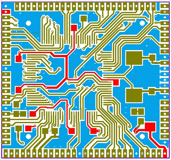
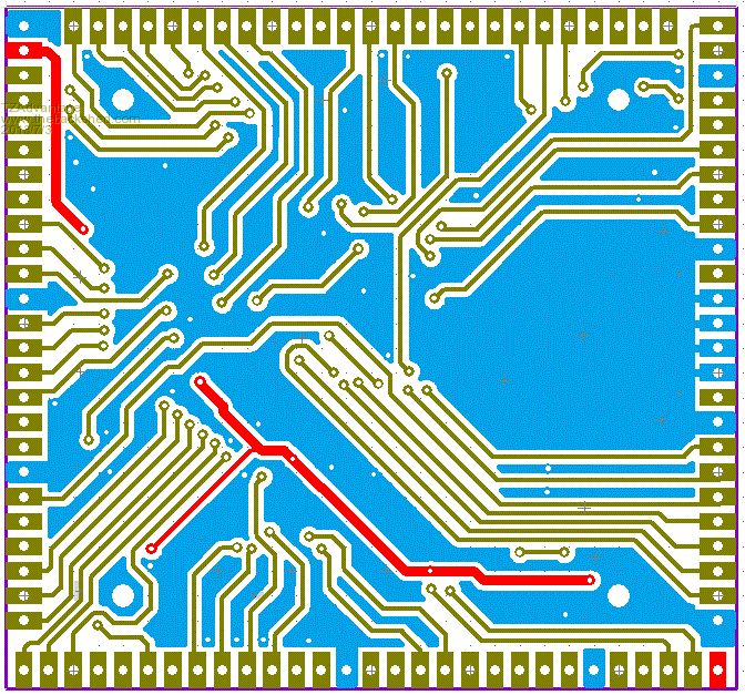
I prefer a single-point-of-origin Vdd, bottom right was where is started as that was the best location for a tank capacitor. Once the signal traces were done i happen to be very close to the top left corner with the Vdd so choose to add a second pin for it.
The Ground plane is primarily very important for the area around and under the crystal. There are also no signal traces in that area. I could use some advice about power planes as it is not my strongest point.
I have made a screen shot of both sides showing the Vdd(3.3v) in red and Vss in blue.
Top:
Bottom:
Edited by TZAdvantage 2013-07-04Microblocks. Build with logic.
paceman Guru Joined: 07/10/2011 Location: AustraliaPosts: 1328
Posted: 03:00am 03 Jul 2013
Copy link to clipboard
Print this post
MicroBlocks Guru Joined: 12/05/2012 Location: ThailandPosts: 2209
Posted: 07:46am 03 Jul 2013
Copy link to clipboard
Print this post
Good point. I also going to change the distance between those points from 20mm to 20.32 mm. That will make it fit a standard 0.1" grid.
I also change two of the four pads (the top left and bottom right) into 3.3v. You would then have the ability to provide the board with power from all sides.
I also going to change the two i2c connectors on the right side and make them available on both 1mm and 0.1" grid. This will allow the use of a 6 wire 'backplane' where the only traces needed are GND, VCC and two sets of SDA and SCL.
Edited by TZAdvantage 2013-07-04Microblocks. Build with logic.
paceman Guru Joined: 07/10/2011 Location: AustraliaPosts: 1328
Posted: 06:26pm 03 Jul 2013
Copy link to clipboard
Print this post
That all sounds good.
A query on the 1mm diameter for those 4 holes (2 Gnd, 2 3.3v). I'm not sure here but 1mm is probably too small for a mounting screw and probably?? too big for either a piggy-back board pin or a test pin. What do you think?
GregEdited by paceman 2013-07-05