
|
|
Forum Index : Microcontroller and PC projects : Knock Detector
| Author | Message | ||||
jman Guru Joined: 12/06/2011 Location: New ZealandPosts: 711 |
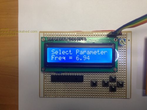
Hi For those like to play with the electronics in their cars. I have been working on a programable Knock Detector using a TPIC8101 from TI This chip been programable via SPI allows us to fine tune the dectection to avoid false detection The folowing parameters are covered Frequency (kHz) This is the frequency that the Knock filter module will listen for knocks at. The knock frequency can be approximated using a simple formula: 900/(Pi * r) where r = the radius of the bore With a bore of 76mm the knock frequency will be 7540Hz Gain Gain is the amount of amplification that is applied to the knock sensor signal before it is processed. Aim to keep the Gain setting as low as you can. A setting of around 0.3 to 0.5 is a good starting point Integration time Integration time is the length of the sample that is processed. The times are in microseconds (1/1000th of a millisecond). Longer integration times will reduce the chance of false knock detection Knock Sensor This setting selects which knock sensor to use. Options are 1, 2 ADC Threshold % This setting determines how �loud� the processed knock signal needs to be before it should be considered a knock event. The setting should be around 65% to 75% Knock Sustain (ms) This setting can be used to �stretch out� knock events. You may want to be extended beyond the length of the actual knock. To use simply hook it up and set the required paramaters To bring up the menu press the right button and the select button to step through the options. The settings are saved to file on the internal drive Once the correct settings have been applied and tested the I2C LCD module can be removed refer to this post for the I2C LCD details I2C LCD 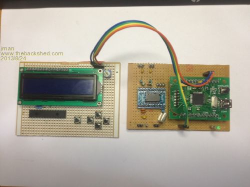
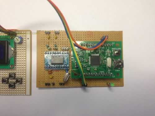
2013-08-24_060119_Knock.zip The Datasheet for the TPIC8101 can be found here TPIC8101 My sample MM code is attached The code is by no means neat and tidy but it works fine Regards Jman |
||||
OA47 Guru Joined: 11/04/2012 Location: AustraliaPosts: 1046 |
Jman, a very good job done. I don't know why there hasn't been other comments (maybe you have blinded them with science :-) I have at least one vehicle with a knock sensor installed from the manufacturer and was wondering how the ECU is set to react when a knock is identified? I have looked through the code and project and you have renewed my interest in some engine related projects. Thanks again for sharing this project. |
||||
| JohnS Guru Joined: 18/11/2011 Location: United KingdomPosts: 4298 |
Mine has knock sensors but if I want to read them I use OBD so need nothing more than a cheap elm327. Still, an interesting post. John |
||||
| jman Guru Joined: 12/06/2011 Location: New ZealandPosts: 711 |
I have yet to see an OBDII that supports knock detection output. The knock detector I made was to enable an LED to reliably show knock so the timing can be adjusted to eliminate it. A lot of after market ECU's have a knock input but no actual knock detector circuit. (These are logic inputs). The Link Knock Detector is a professional unit but costs a lot more than the DIY approach Of course the best part of doing yourself is that you can customize the software and hardware to suit your requirements. Regards John |
||||
| JohnS Guru Joined: 18/11/2011 Location: United KingdomPosts: 4298 |
Quite a few of the tuner tools and many make-specific tools work. They tend to be mode 22 things. It helps to get something the PCM has already sanitised by removing noise and on a good day isolated per cylinder. John |
||||
| westie42 Newbie Joined: 25/09/2017 Location: New ZealandPosts: 3 |
hi jman would you believe this is the exact circuit im trying to build ?, thanks so much for posting it i have an aftermarket ECU with a knock input but it needs a conditioner , perfect the other problem i have is i left learning coding about 30 years to late .... i would be most great full for any advice so far i have built and tested the mini maximite and a board with the mcp23017 and lcd together with the tpic8101 based on your photos i am using MM edit to load and run the code to the mini maximite when i couldent get anything to run i loaded your I2C LCD code and was greeted with a HELLO WORLD once i changed the 12c commands in your program to the newer i2c OPEN i2c CLOSE ect .so that proves the hardware works - other than the buttons would not respond i can see from your photos that your code works so its something im doing wrong i see that you wrote the code in 2013 and that MM firmware has had many revisions should i use an older version to run with your code ? this is also my first foray into online forums so i shall tread very carefully and try not to do anything wrong , there seems to be a lot of very knowledgeable people here so hopefully someone can point me in the right direction any advice would be most appreciated thankyou mike |
||||
| The Back Shed's forum code is written, and hosted, in Australia. | © JAQ Software 2026 |
