
|
|
Forum Index : Microcontroller and PC projects : I2C LCD
| Author | Message | ||||
| MOBI Guru Joined: 02/12/2012 Location: AustraliaPosts: 819 |
Just curious, is anyone following my dribblings? or just curious or .....? I've got the module running as a i2c blank, i.e. I can write to and read from a bank of 8 registers in the slave but I still have to put in the main function that actually does something with the register data e.g. LCD driver. At the moment, it is just a 8 byte i2c memory - wow 
David M. |
||||
Grogster Admin Group Joined: 31/12/2012 Location: New ZealandPosts: 9082 |
Have read all your dribblings thus far.  Smoke makes things work. When the smoke gets out, it stops! |
||||
Bryan1 Guru Joined: 22/02/2006 Location: AustraliaPosts: 1213 |
+1 reading this thread when I see it's updated and now off to the shed to start getting this BB together now those caps turned up..... |
||||
| MicroBlocks Guru Joined: 12/05/2012 Location: ThailandPosts: 2209 |
I read all your dribblings. :) Having a I2C template with 8 registers is a great way to start a I2C device. Only adding a main and filling those registers with the right values and your done. As for connecting a LCD to the PIC, i made a schematic some time ago to figure out the connections. My goal was to have the smallest pic capable of doing it (as you can see in the schematics, all pins are used. Here is the pdf: 2014-01-23_070930_LCD_OLED.dch.pdf Microblocks. Build with logic. |
||||
| MOBI Guru Joined: 02/12/2012 Location: AustraliaPosts: 819 |
@TZA That is essentially what I came up with - great minds? Instead of dedicated ICSP pins, I opted for jumpers which left 2 pins for user selectable address lines - up to 4 displays at a time. PS. I meant to ask, did you ever get the firmware written? David M. |
||||
| MicroBlocks Guru Joined: 12/05/2012 Location: ThailandPosts: 2209 |
hi Mobi, i have made some lcd 'firmware' before but that was for a picaxe and i am unable to find the code.... Basically i tried to get most of the complexity of controlling an lcd into it so that a mcu using it can just send simple text and commands. I remember i used escape codes to send commands. like Esc followed by 0x80 meant clear screen, esc followed by 0x81 meant move cursor to line 1, etc that worked pretty good and was very easy to use from a mcu. i also had fixed messages stored in flash that i could access through an Esc code. This helped saving memory in the main mcu. Are you familiar with how character lcds work with 4 bits? If you want i can try to find which initialisation i used in other instances i used an lcd. Microblocks. Build with logic. |
||||
jman Guru Joined: 12/06/2011 Location: New ZealandPosts: 711 |
I have firmware for a serial LCD backpack written in PBP It use's a PIC 16F628a but can be complied for any device with a uart A serial buffer is included To write to the LCD is real easy Print #5;"Text goes here"; Will print "Text goes here" on the LCD Control codes are $hFE so Print #5;Chr$(254);Chr$(1); "Line 1 pos 0 Print #5;"Line 1"; Print #5;Chr$(254);Chr$(&HC0); "Line 2 pos 0 Print #5;" Line 2"; Print #5;Chr$(254);Chr$(&H96); "Line 3 pos 3 Print #5;"Line 3"; Print #5;Chr$(254);Chr$(&HD4); "Line 4 pos 0 Print #5;"Line 4"; And a to control the backlight Print #5;Chr$(124);Chr$(128); "Step backlight brightness use 128 - 157" If the backlight level changes the new value will get written to eeprom and used at next power up I can post the PBP code if required Regards John |
||||
| MOBI Guru Joined: 02/12/2012 Location: AustraliaPosts: 819 |
Certainly. I built an i2c lcd based on the pic16f88/819 about 6 years ago. I was just wondering if anyone on the forum had done likewise. The code to drive the display is really quite simple. As I recall, the hard part was trying to understand the documentation written in "Chinglish" I never saw any need to make the back light variable intensity, on or off was usually enough. Mind you, if desired, is easy enough to accommodate but my motto is "kiss". When I have translated the F88/819 code to F1503, I'll put it in a zip file for those crazy enough to work through assembly code. David M. |
||||
| MOBI Guru Joined: 02/12/2012 Location: AustraliaPosts: 819 |
@TZAdvantage et al. Yippee!!! It works. It developed a few bugs in the firmware during translation because the D4 to D7 on the LCD were displaced by two bits as our Port C started at bit C2 not zero. (C0 and C1 are the SCL and SDA pins) Then I had a couple of MOVLWs instead of MOVWFs and wondered why the data was going nowhere. I'll need to build in a control register check for screen backlight on/off and code that in. OOPs, I better go back and un-comment the user select address function and set the base address to "standard" LCD device code of "01110aax". Then I'll tidy up the source code, break it up into blocks and zip it. Thought I'd chuck in a couple of photos. 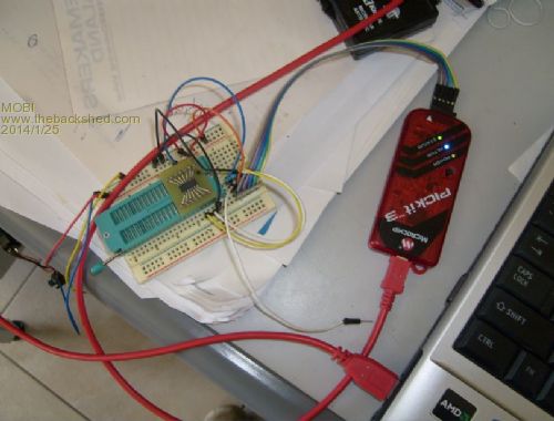
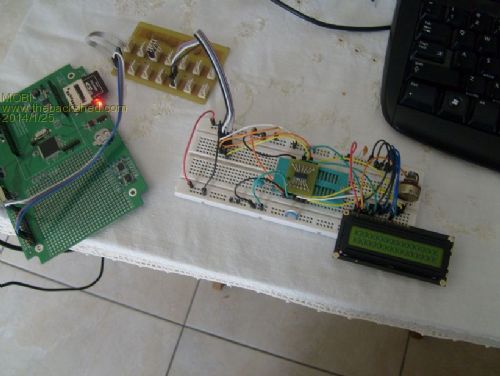
David M. |
||||
| MicroBlocks Guru Joined: 12/05/2012 Location: ThailandPosts: 2209 |
That is a great result. Time to brush up my assembly language knowledge. Microblocks. Build with logic. |
||||
| MOBI Guru Joined: 02/12/2012 Location: AustraliaPosts: 819 |
@TZAdvantage As requested, I've altered the code to fit your schematic and also coded a PWM back light brightness control. I limited the PWM to 8 bits instead of 10 bits and the possible 1024 steps. So that is 256 steps 0 to 255 full off to full on. I thought that would be smooth enough for the eye not to see the steps as the back light is wound up and down. The data is sent in the format: Register address, control byte, value byte. Value byte is the character, instruction or backlight PWM duty cycle number. The control byte determines the function to be performed. It is a pretty basic display but I think will do just about all you want to do with it. I originally built it for my RFID cattle ear tag reader and didn't need fancy graphics. David M. |
||||
