
|
|
Forum Index : Microcontroller and PC projects : MicroMite Elevator...
| Page 1 of 3 |
|||||
| Author | Message | ||||
Grogster Admin Group Joined: 31/12/2012 Location: New ZealandPosts: 9974 |
Something I was always going to play with, was a model elevator. When you look at the old control systems and motor-rooms for elevators from the 60's to late 70's, they are a thing of beauty. Usually not even a single transistor in the thing, just hundreds of relays and contactors, and one hell of a lot of interconnecting wires!!! Take this beautiful example of a relay-logic controlled elevator, sadly, no longer with us..... Relay-logic Elevator Now, while the relay control IS a thing of beauty, and more then just a little fascinating to watch in operation, micro-controllers have well and truly taken over with elevator control. So I thought I might try to make a model of one, and use the MicroMite as the controller. I am still looking at options, but if I kept the model to four "Floors" or less, then I think we could do it all with the 44-pin uM. I am just throwing the idea about, as something new to learn, and another way of playing around with MMBasic. Smoke makes things work. When the smoke gets out, it stops! |
||||
| viscomjim Guru Joined: 08/01/2014 Location: United StatesPosts: 925 |
Hi Grogster, Very cool video. Could you imagine what it took to design that contraption? I couldn't even begin to. Crazy that it probably could be implemented with a very small microcontroller today and probably is somewhere. I'm sure otis elevator has some cool hardware and firmware behind what they do. If you do proceed with the elevator simulator or elsim is I like to call it, please post, as I'm sure the code would be of value for other things. |
||||
| Grogster Admin Group Joined: 31/12/2012 Location: New ZealandPosts: 9974 |
Re the relay logic elevator video - yeah, I have watched that more then a couple of times, and you are so right - imagine having to design or fault-find those things! Surprisingly, those old lifts' relay logic seemed very reliable indeed, as evidenced by the fact that there are still a few of them running. For those interested in those facinating relay-logic systems, and an expansion on that idea using a kind of daisy-wheel-switch-thing for the floor-detector and car-leveller, have a look at this fascinating video: Lift, part 1 Lift, part 2 He's a bit naughty, as I don't think he's supposed/authorised to be in these motor rooms, but he does seem to know what he is talking about - just don't copy him! On the code, yes, I will post as I go. I have a couple of ideas for how I plan to build this thing. I would like to employ car slow-down, door bells etc. A nice project for the dull evenings, now that I have decided to drop the booze...(you have to have something to keep your mind on other things) Smoke makes things work. When the smoke gets out, it stops! |
||||
| Geoffg Guru Joined: 06/06/2011 Location: AustraliaPosts: 3362 |
I have always wanted to do something similar (but never got around to it). If you were going to do a model of a large building with multiple cars you would then have the interesting aspect of optimising the movements of the cars. For example, for the morning peak time you would like most cars to end up at the ground floor. With just a single lift and four floors it will be complex enough, getting a smooth acceleration, responding to calls, etc. Geoff Geoff Graham - http://geoffg.net |
||||
bigmik Guru Joined: 20/06/2011 Location: AustraliaPosts: 2981 |
Groggy, All, Don and I used to service, as part of our normal day to day duties, incandescent indicator boards that would show the Betting ODDs of upto 24 horses/runners. These were ALL relay driven, the oldest (and worst to service IMHO were the ones using `3000series' relays. They used a `relay logic' "3 out of 5 or 5 out of 7", DOn could provide more information as I am sure he designed them back in the 1800's 
These were a piece of electromechanical marvel, but a nightmare to work on. Thank goodness it is all electronic these days.. Incidentally Logic, almost identical to digital logic, is used in Pneumatics as well. Regards, Mick Mick's uMite Stuff can be found >>> HERE (Kindly hosted by Dontronics) <<< |
||||
donmck Guru Joined: 09/06/2011 Location: AustraliaPosts: 1314 |
Not quite the 1800's Mick, but close. I did design on course (TAB) betting systems using relay logic. In a previous life, I went through the PMG relay-uniselector logic that was used in early telephone exchanges of the fifties, so I had good grounding for relay driven logic. To me, the migration process from electro-mechanical systems, to computers was an easy one. I'll bet many older TBS members went along the same path as me. I read this thread with interest, as I had similar thoughts about an old pin ball machine I had. It always needed adjusting, and I promised myself I would run it from a Motorola 6800 micro, the only micro I had access to at the time. A development programmer I was working with at the time, offered me enough money for me to let it go, so off it went. I believe it can be seen today living in a farmers rubbish dump in Kyogle, New South Wales. Years later I rigged up the front panel of a PDP 11/40 system so that it would emulate the normal operating conditions of the address and data LEDs. I had that running on a Z80 system. This ran for many years at our project development site at Moonee Valley racecourse, and it amused many IT visitors that had never seen a real computer system. :-) I still have it around here somewhere, but never did a video of it operating. Perhaps I should go have a look for it and see if it smokes or runs. The thought had crossed my mind on how easy it would be to run it from a USB power supply via a micromite to drive the 11/40 address and data LED emulation. Maybe one day :-) Cheers Don... https://www.dontronics.com |
||||
| Grogster Admin Group Joined: 31/12/2012 Location: New ZealandPosts: 9974 |
Well, I know at least one person has made a bloody good model. Check out this video: Model elevator There is a little fella talking on the video, so expect kid-talk to some extent, but you can see how beautifully made this thing is. Not sure I can compete with that, but I will play with some ideas. The first thing to get working, will be some kind of car in a shaft, with interrupt switches to tell the uM when to stop the motor etc. I was thinking of using a transistor H bridge to drive the motor, but am now wondering if I should just use a standard DPDT relay, and drive that from the uM, as that only needs one pin, whereas the H bridge needs two control pins.... Smoke makes things work. When the smoke gets out, it stops! |
||||
| bigfix Senior Member Joined: 20/02/2014 Location: AustriaPosts: 130 |
About the 11/40 from Don... I worked for DEC nearly 20 Years, doing 11/70s in the beginning They have an even fancier switch panel than a 11/40 When I left, I took one as a souvenir (together with a huge wirewrapped backplane) To my big surprise some years later I found a young guy at the Computer Museum in Mountainview California. He was showing a custom USB interface for a 11/70 Panel interfacing to a PDP11 Emulator on a laptop I bought his spare version - but never made it into a neat system Still on the todo list ! |
||||
| donmck Guru Joined: 09/06/2011 Location: AustraliaPosts: 1314 |
It had been suggested that we offer my unit to DEC for a display in the foyer at Box Hill here in Australia, but I never got around to it. I had also thought of doing the same for the Science Works Museum here in Melbourne. 11/70, yes I know it, we went onto 11/34s eventually (before VAXs etc.), but the front panel of course was nothing compared to the bells and whistles of the earlier ones like the 70s and 40s. I have what I remember as being an 11/05 Front Panel around here somewhere also. I'll have to check. Cheers Don... https://www.dontronics.com |
||||
| bigfix Senior Member Joined: 20/02/2014 Location: AustriaPosts: 130 |
I still have a 11/34 with real magnetic core memory, 9 inch tape and 8 inch floppies... You are right the 11/34 frontpanel is rather boring But it is based on the rare PMOS 8008 chip - Vintage by itself I did not power it on for many years though... |
||||
| Grogster Admin Group Joined: 31/12/2012 Location: New ZealandPosts: 9974 |
Initial investigation on what I am going to need, indicates at least 31 I/O pins for a four storey elevator, including slow-down sensors for each floor, indicator lights(LED's) for cabin position on each floor, buttons on each floor, UP/DN arrow lights on each floor, door open/close, and motor control. So, at this stage, I am moving the project to the full-size colour MM due to lack of I/O pins on the uM. I probably could do it with the uM, if I was to adopt I2C or other interface to send data to the controller - that would cut down on the number of I/O pins needed - still thinking about that. The original idea, was to keep it as basic as possible, by just having ONE central controller, and then all your switches in the shaft and cabin etc - just like a bought one! The advantage of using the colour MM is that I can also then write code to show on the screen what the controller thinks it is doing with the elevator etc. I could use the uM with the likes of one of those Microchip I2C IO port multiplier chips, but as the full-size MM has 40 IO pins to play with already.....(however, that could still be done later perhaps?) I should mention that I consider a four-storey lift, to actually be five physical levels: Ground, 1, 2, 3, and 4. EDIT: Revising the numbers, I am back down a bit in the IO pins, by paralleling up certain thing common to each floor. uM is back on the table. Smoke makes things work. When the smoke gets out, it stops! |
||||
| Grogster Admin Group Joined: 31/12/2012 Location: New ZealandPosts: 9974 |
These are the numbers I have come up with so far: UP/DN motor reverser - 1 pin(use DPDT relay) UP/DN motor speed control - 1 pin(use PWM for speed control) UP/DN ARROW LIGHTS - 2 pins(two arrows for each floor panel, paralleled up) OPEN/CLOSE door motor reverser - 1 pin(DPDT relay) OPEN/CLOSE door motor control - 1 pin(use PWM for speed control) OPEN/CLOSE door sensor - 2 pins(one for open, one for closed) CABIN IR DOOR BEAM - 1 pin(don't close doors on people!) FLOOR sensors - 5 pins(one for each floor) CAR LEVEL sensors - 5 pins(one for each floor) SLOW DOWN sensors - 5 pins(one for each floor, two sensors; upper and lower) FLOOR BUTTONS - 5 pins(one SET for each floor panel) FLOOR INDICATORS - 5 pins(one SET for each floor panel) Total IO pins so far: 34 Can anyone think of anything else I have missed? I guess it depends on how complicated you want to make things, doesn't it?(rhetorical) This is one more pin then the uM has available in the 44-pin version, so I will see if I can shave one more pin off - either that, or I will make my building one storey smaller then I planned to build it.  That will free up enough pins to make it workable on the 44-pin uM. That will free up enough pins to make it workable on the 44-pin uM.Smoke makes things work. When the smoke gets out, it stops! |
||||
| bigmik Guru Joined: 20/06/2011 Location: AustraliaPosts: 2981 |
Hi Groggy, Sounds impressive, have you thought about using two uMtes talking to each other via I2C or serial or IR or wireless? They are so cheap its a no brainer. Split the load but use one as the main control and the slave for buttons and lights and emergency sprinkler system. 
Regards, Mick. Mick's uMite Stuff can be found >>> HERE (Kindly hosted by Dontronics) <<< |
||||
| Grogster Admin Group Joined: 31/12/2012 Location: New ZealandPosts: 9974 |
Meh - this concept is now in the bin. I will start fresh, just keeping it simple for a start, THEN I can add in the extra cute features. Easier to get working too. So, I will just concentrate on cabin control and sensors for now - no slow-down sensors, no pretty lights or anything like that. So easy to over-complicate your projects sometimes!!! EDIT: @ Mick - Yeah, I did think about that, but my concern was I would be over-complicating things - which I seem to have done anyway!!!!
Blank page, everybody. I DO like that I2C master/slave idea though, Mick, and I am sure if MOBI is reading this, he too would approve of the I2C thing. I need to learn more I2C, so this would be a perfect way for me to do some of that. As you say - have a main controller(master), and the button-and-sensor processor(the slave), and link them together. I might even get clever and use three uM chips/modules on I2C. One master controller, and two slave units. One slave could process inputs like sensor switches etc, and the other one could be outputs like motor control, door control, indicator lights etc..... Smoke makes things work. When the smoke gets out, it stops! |
||||
| bigmik Guru Joined: 20/06/2011 Location: AustraliaPosts: 2981 |
Groggy, Just a thought while sitting here watching 'the idiot box'. You could drive the two leds from one pin. Set up two transistor drive circuits off the pin one that sets an led on when high and the other on when low. By using a resistor divider on the base of the transistor and setting the pin as an input you could turn off both leds. Regards, Mick Mick's uMite Stuff can be found >>> HERE (Kindly hosted by Dontronics) <<< |
||||
| Grogster Admin Group Joined: 31/12/2012 Location: New ZealandPosts: 9974 |
I guess you mean something like this? 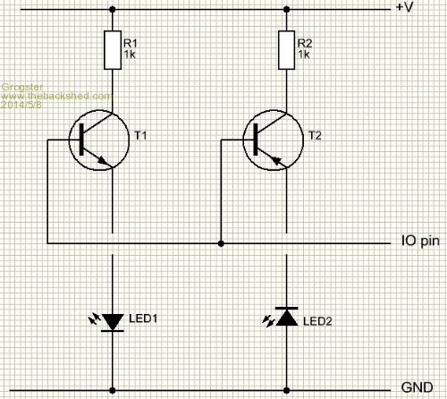
That would certainly work for two LED's on one IO pin. If you make the IO pin connected to the two bases an input, I would expect that this would turn off both LED's. Come to think of it, it probably won't, as there are internal 10k pullups inside the PIC I think. If that is the case, even as an input, the pin will be high, which would keep one of the LED's on. I would have to build it on the bench to test it out, but it is possible that it could work. If I use two or three uM chips in an I2C arragement as mentioned, I should then have plenty of IO pins. Smoke makes things work. When the smoke gets out, it stops! |
||||
| bigmik Guru Joined: 20/06/2011 Location: AustraliaPosts: 2981 |
Groggy, Not quite.. You will never get led2 to light as +ve needs to go to the anode, which you connected to gnd.. But the general idea is correct... I will do a cct for you if i get a chance tomorrow.. As for turning on one led when set as an input that is why the divider is to bias both off.. I need to think a bit more myself, i am not in that frame of mind at the moment.. Hey that means I am groggy myself.
Regards, Mick Mick's uMite Stuff can be found >>> HERE (Kindly hosted by Dontronics) <<< |
||||
| Grogster Admin Group Joined: 31/12/2012 Location: New ZealandPosts: 9974 |
How about this? 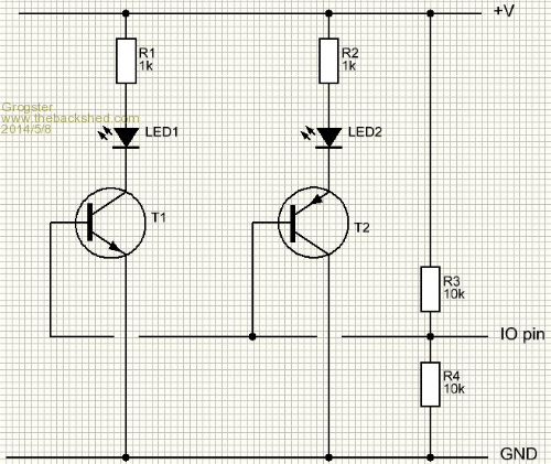
I am still not sure about the bases of the transistors in this arrangement.... Oh well - does not matter to me really, you have just made me curious Mick!!!! 
See ya'all tomorrow - midnight or so here, and the Grogster needs sleep.  Smoke makes things work. When the smoke gets out, it stops! |
||||
| bigmik Guru Joined: 20/06/2011 Location: AustraliaPosts: 2981 |
Grogs, Actually thinking about this, if you use high intensity leds with a fwd voltage drop of 2.2v or so, Put them in series and connect the loose anode to 3.3v and the loose cathode to gnd then connect your io pin to the junction via a 100R resistor that might be all you need.. As the max voltage you could get across is 3.3/2 or 1.65 volt when the io is input i reckon no Led will light. Drop the Resistor to about 22R when 5 Leds in parallel,.. Maybe have to trial resistor values, Mick Mick's uMite Stuff can be found >>> HERE (Kindly hosted by Dontronics) <<< |
||||
| Grogster Admin Group Joined: 31/12/2012 Location: New ZealandPosts: 9974 |
Ahhhhhhh - you mean like this: 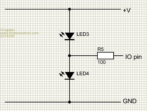
If the IO pin is an output, and is high, LED4 will light, but LED3 will be reverse-biased, so will remain off. If the IO pin is an output, and is low, LED3 will light, but LED4 will be reverse-biased, so will remain off. If the IO pin is an input, there is insufficient voltage on the input pin to forward-bias either LED, so they are both off. I will try this tomorrow on the breadboard.... Smoke makes things work. When the smoke gets out, it stops! |
||||
| Page 1 of 3 |
|||||
| The Back Shed's forum code is written, and hosted, in Australia. | © JAQ Software 2026 |
