
|
|
Forum Index : Microcontroller and PC projects : uMite Tester PCB
| Author | Message | ||||
bigmik Guru Joined: 20/06/2011 Location: AustraliaPosts: 2981 |
Hi All, As I have built up a few of my MuPs I did a breadboard with 19LEDs to test the ones that I built. Now I am happy that every pin at least has connectivity to the PIC32 and that the PIC32 seems to be functional. I have found it quite invaluable so I wonder if there would be demand for such a PCB.. I envisage that it would be about 18mm x 38mm and has 19 x 3mm LEDs and either one or 19 resistors. I used one resistor which is fine for an LED chase as there is only one LED on at any time but with 19 resistors all of them could be on at the same time (max current limits permitting). I envisage that these could be sold at about $1ea, which means the postage would likely be more than the board. Now I have two questions. 1. Is there a demand for this? 2. Are there some simple additions that could be added to make this PCB a bit more `usable' so its not a use once and put aside board? Ideas I am toying with include making a mini Test-A-Mite Although this is likely to increase the size a little it would enable analog and count/period/frequency testing to be done (as does the TaM does for the Maximite. Any ideas? Any Interest? Regards, Mick Mick's uMite Stuff can be found >>> HERE (Kindly hosted by Dontronics) <<< |
||||
halldave Senior Member Joined: 04/05/2014 Location: AustraliaPosts: 121 |
1. I would be interested in a couple |
||||
Grogster Admin Group Joined: 31/12/2012 Location: New ZealandPosts: 9975 |
I am most likely missing something important, but can you explain WHY you would need a device like this? I must have soldered hundreds of chips in my years thus far, both through-hole DIP and SMD packages(before and after WW's method), and I have never ever had faulty pins or I/O pins on a microcontroller that were not working. I have managed to kill MCU's myself through stupid things I have done, but with a new chip, I would be extremely surprised indeed, to find any I/O pin not working from first fire-up, assuming that you took all necessary anti-static and soldering precautions. This is not to say that cos I have not had that happen to me, that it could not EVER happen to me, naturally - perhaps I have just been lucky to date?! 
Is it more for testing that the SMD soldering to the chip is correct and that you have conductivity? Perhaps aimed more at SMD testing more then anything? Smoke makes things work. When the smoke gets out, it stops! |
||||
| bigmik Guru Joined: 20/06/2011 Location: AustraliaPosts: 2981 |
Hi Groggy, NEED it? Nope, it is, of course not necessary to have one, indeed in the form proposed it has limitted use. USEFUL? Yes, I believe so. I have a bread-boarded one that I use for testing my built up MuPs.. I find it very useful and comforting to know that every pin is working and that there are no SHORTED or OPEN pins. I have been building bits and bobs for about 40 years now and still find it satisfying to prove to myself that my build was successful. Indeed I am sure that there will be those who build one up and will solder `splash' across a couple of pins and wonder why their `all singing all dancing' program doesnt work as expected. A one minute plug in of the tester will allay any (well most anyway) fears of a build problem. The Test-A-Mite board I made for Dontronics was IMHO more than a simple LED chaser demo board. I feel that it was never recognised as the versatile software debug/development tool that I feel that it is. Sure not in the same vein as a logic analyser or CRO. But the T-A-M could not only control an LED on every pin (emulating say driving a Relay for instance) it could apply a High or Low to be sensed as an input (emulating a sensor trigger) it could be used to apply a H-L or L-H trigger to test your code or test the count/freq/period inputs.. Sure not a 100% requirement but sometimes LEDs can tell you a lot. I digress, I am not really proposing this as a Mini T-A-M anyway (that would probably be better suited by an adapter to match the 20 IO pins of the T-A-M to the uMite. I posted this thread to gauge how much interest there was in an LED test PCB. To date we have: Yes 1 No 1 So, I think the answer is looking to be more along the line of insufficient need seen out there to warrant its creation than not. If that is the case what I will do is post a circuit and a simple test program for those who need one to bread-board their own (which, of course, I would do anyway even if the tester was a reality). Regards, Mick Mick's uMite Stuff can be found >>> HERE (Kindly hosted by Dontronics) <<< |
||||
| Grogster Admin Group Joined: 31/12/2012 Location: New ZealandPosts: 9975 |
I was not really saying no. I was just curious as to why you would want one - that does not make it a bad idea, just cos I was unaware of it's usefullness. Your post above has clarified it actually, and I can certainly see that it could be useful for the purposes of bench-testing. Especially if you are assembling units to post to someone else - it would work as a form of quality control check. Smoke makes things work. When the smoke gets out, it stops! |
||||
| bigmik Guru Joined: 20/06/2011 Location: AustraliaPosts: 2981 |
Hi Grogs, Thats fine even if you did say no, sorry if my `tally' upset you.. 
Exactly MY need for one, but then I have one bread-boarded, I was also wondering what else could be added with minimal space impact IF I did commit it to fibre-glass. Regards, Mick Mick's uMite Stuff can be found >>> HERE (Kindly hosted by Dontronics) <<< |
||||
| WhiteWizzard Guru Joined: 05/04/2013 Location: United KingdomPosts: 2991 |
This kind of 'test unit' is invaluable when checking the integrity of a MicroMite Module. I use something similar for testing every 44-pin MicroMite module I despatch. The main purpose is to test connectivity of the SMD PIC pins - it is not for testing a pin's functions (everyone's Beta testing checked this!). I don't see much use other than a test unit which is why I haven't manufactured a PCB. This unit was built on some spare veroboard and only took an hour to create - and I use it every day! 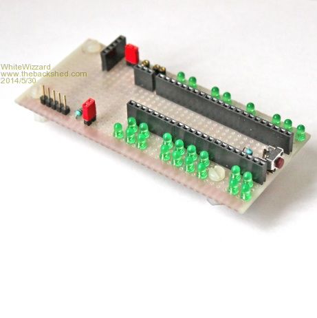
This unit allows me to test a MicroMite Lite (i.e just the PIC + caps on a PCB) or a fully featured MicroMite module. With regards to a MicroMite Lite, various permutations are available: with/without reset switch; with/without ICSP. This is why I have included an onboard ICSP (lower left) and reset button - i.e. in case the Lite under test doesn't have them fitted as options BUT I still test the functionality in case the end-user installs it themselves. 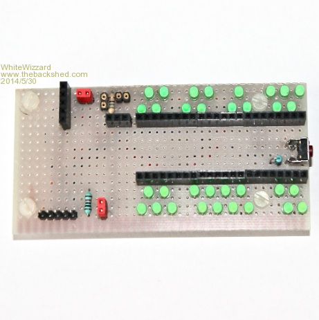
(Note: these are not self-powered LEDs - just reflecting the camera's flash!) I simply load a test program using MMEdit which pulses each of the 33 pins high, one at a time, with a short delay between each pin (to allow me to see the LED on). I have 'staggered' the LEDs so it is visually obvious if a pin is open-circuit (your brain expects to see a zig-zag pattern - if one pin is not connected then you 'see' it much more clearly than if the LEDs are in a straight row (useful tip!)). 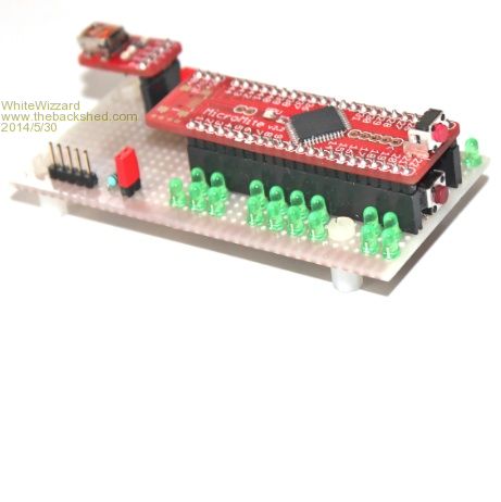
Here I am testing a Lite with no ICSP but it does have a reset switch fitted. You can see the USB Module used to communicate with the MicroMite plugged into the header in top-left of unit. If testing a fully featured MicroMite then no USB module is used. 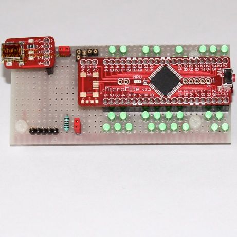
Test points around the USB module header allow me to check 5v and 3v3 levels. So in summary - the most valuable tool EVER for checking my MicroMites prior to despatch. I have logic analysers and various MultiMeters but this is so quick and easy to use and does a full check. And a major UK PCB company that I am in discussion with about assembling the MicroMite for me has seen this test unit and thought it was a very 'smart yet simple' piece of test kit and wish to make some for their internal test procedures! WW |
||||
| Grogster Admin Group Joined: 31/12/2012 Location: New ZealandPosts: 9975 |
Oh Hell - I am making it worse!!!!!!! 
Certainly did not upset me - takes a-lot more then that! Smoke makes things work. When the smoke gets out, it stops! |
||||
| bigmik Guru Joined: 20/06/2011 Location: AustraliaPosts: 2981 |
Hi All, OK I have done a design, of course this really only goes with my MuP boards, you would need to make an adapter to suit the pinout of whatever other flavour of uMite you need to test. I think I will get a few done (probably ony a dozen or so).. I will get some quotes with details later.. But here is the overlay. 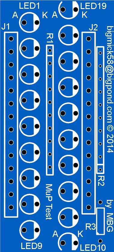
and the Schematic: 2014-06-02_072841_MuP_Test_Schematic.pdf I will try the "dirty crumby rotten PCBs" that Jman mentioned earlier and see what we can get them down to. The size is only 22.5mm x 49.5mm so we can get two per 50mmx50mm layout or 8 per 100mmx100mm layout but they would need to be cut (carefully some tracks are close to the edge.. Regards, Mick EDIT*** Hey how come the JPEG image is so big this time? How does that work? When you want a nice big picture you cant get one but when it doesnt really matter it zooms up. Mick Mick's uMite Stuff can be found >>> HERE (Kindly hosted by Dontronics) <<< |
||||
| vasi Guru Joined: 23/03/2007 Location: RomaniaPosts: 1697 |
Is not big!  the width is 500px or less. the width is 500px or less.Hobbit name: Togo Toadfoot of Frogmorton Elvish name: Mablung Miriel Beyound Arduino Lang |
||||
| halldave Senior Member Joined: 04/05/2014 Location: AustraliaPosts: 121 |
put me down for 1 |
||||
| WhiteWizzard Guru Joined: 05/04/2013 Location: United KingdomPosts: 2991 |
Looks good Mick, I will take an Airmail worth!! Two things: 1> Is this a double-sided PCB to allow the LEDs (or connectors) being on the 'opposite' side of the board so that all the LEDs can be seen when this PCB is connected to the MuP? 2> J2 pin 10 to ground - is this correct? From memory this is Vcap isn't it? (I am not next to a MuP at the moment to check this myself so just wanted to highlight this as a possible error (apologies if I have remembered this incorrectly) WW |
||||
| bigmik Guru Joined: 20/06/2011 Location: AustraliaPosts: 2981 |
Hi Phil, All, 1. YES! it is a double side board with copper pour both sides (mainly for strength and stability as it it to be plugged in and out many times.. 2. Pin 20 is GND because the MuP header pins were designed so that pin 20 (Vcap+) did NOT come out onto the bus, I thought about putting 5V there but decided on another GND, a solitary 5V pin in the middle of the line up, I felt, was a bit dangerous if anything was misaligned when plugged in.. I had a look at `Dirty Crappy rotten junko PCBs' and to `panelise' every board must be connected via some tracks to each other, I cant seem to work out how to panelise with AUTOTRAX but I will keep looking.. Will keep you all informed when I have some ideas of costs, maybe only looking at 25 or so, at least initially.. I dont see these being a big seller. Regards, Mick EDIT*** Yes the connections to the MuP, are bottom mounted, and the LEDs, resistor and 2 x resistor packs are top mounted.. Which just reminded me, I made those pads holes a bit smaller visualising that they would be FEMALE only but of course you may have made MuP with Females so you need to be able to put MALEs there. I will fix that before I get any made. Regards, mick Mick's uMite Stuff can be found >>> HERE (Kindly hosted by Dontronics) <<< |
||||
| The Back Shed's forum code is written, and hosted, in Australia. | © JAQ Software 2026 |
