
|
|
Forum Index : Microcontroller and PC projects : WakeUP
| Author | Message | ||||
jman Guru Joined: 12/06/2011 Location: New ZealandPosts: 711 |
Hi Does anybody know or have a method to calculate the capacitor value mentioned in the Micromite manual used to wake the Micromite up. A table with Sleep time and capacitor values would be a great addition to the manual (For those like me anyway) I have a battery powered circuit that would benefit greatly from the power saving Thanks Jman |
||||
Grogster Admin Group Joined: 31/12/2012 Location: New ZealandPosts: 9975 |
Although not the best method, perhaps, how about trial-and-error? You could start with something along the lines of 1uF and see if that does what you need, and then change the cap up or down running the same test till it does work how you want. Smoke makes things work. When the smoke gets out, it stops! |
||||
crez Senior Member Joined: 24/10/2012 Location: AustraliaPosts: 153 |
If you are already using the RTC chip, check my post MICROMITE RTC WAKEUP. This allows accurate wakeup times with only 3uA extra current draw while sleeping. This arrangement would suit something like a data logger that takes readings at regular intervals. David |
||||
| Goeytex Regular Member Joined: 12/05/2014 Location: United StatesPosts: 74 |
Posted by jman: |
||||
| Goeytex Regular Member Joined: 12/05/2014 Location: United StatesPosts: 74 |
UPDATE: It seems that when the pin is changed to an input and the cap discharges, that the voltage will never drop low enough to change the state of the pin without some kind of added load. Probably due to internal leakage current. So I added a 10Meg resistor from the Sleep Pin to ground. Now the pin changes states and this resulted in: 1.1 uf = 14 seconds (tant) 2.2 uf = 28 seconds (tant) 10 uf = 127 seconds (Elect) 45 uf = 563 seconds (tant) Looks fairly linear ... @ about 13 seconds per microfarad with a 10Meg pulldown |
||||
| jman Guru Joined: 12/06/2011 Location: New ZealandPosts: 711 |
Thanks for the tip guys Goeytex your cap/resistor idea works like a charm I never had 10M resistor in the junk box so I used a 2.2M and a 100uf (electrolytic) and this gives me about 190 seconds and that's perfect for the current task Regards Jman |
||||
TassyJim Guru Joined: 07/08/2011 Location: AustraliaPosts: 6538 |
Using a large value capacitor uses up a lot of energy recharging it. The power has to come out of the micromite pin and could be overloading it for a bit too long. I would try a 0.1uF or smaller without any bleed resistor to see what times you achieve. Jim VK7JH MMedit |
||||
| Goeytex Regular Member Joined: 12/05/2014 Location: United StatesPosts: 74 |
It will likely never drop low enough to change the pin state. It won't on mine. Not without some kind of minimal load. Of course you can't read it with a scope because the scope has enough impedance to bring it low and make it appear to work. To prevent surge current to a large cap a, 220 ohm resister can be placed between the pin and the + side of the cap. Just make sure that the Micromite Pin is high long enough to fully charge the cap before going to sleep. |
||||
| TassyJim Guru Joined: 07/08/2011 Location: AustraliaPosts: 6538 |
After a few tests, I agree. With 5pF it takes more than 10 minutes and we are getting into the unpredictable areas. The time would depend on the leakage currents on the circuit board so would be all over the place! Stick to 10 meg ohms or less to get consistent times. For long times it would be OK to have short times and a software counter to know if it's time to do the main events or just increment the timer and go back to sleep. Jim VK7JH MMedit |
||||
| PicFan Senior Member Joined: 18/03/2014 Location: AustriaPosts: 133 |
I have tried the following and it works well. 220 ohms in series to a 1uF tantalum capacitor. Anti-parallel to the capacitor, a diode 1N4148. The leakage current of the diode compensates the leakage current of the uP Pin. Delay: 1uF = 240 sek. |
||||
bigmik Guru Joined: 20/06/2011 Location: AustraliaPosts: 2981 |
Hi PicFan, Have you got a schematic (even a photo of a sketch) as I am a bit confused as to how this is hooked up? What do you mean by ANTI-PARALLEL? Do you mean reverse BIASED? Regards, Mick Mick's uMite Stuff can be found >>> HERE (Kindly hosted by Dontronics) <<< |
||||
| PicFan Senior Member Joined: 18/03/2014 Location: AustriaPosts: 133 |
Hi bigmik, Best regards from Austria - Tirol ! Wolfgang 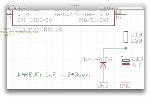
|
||||
| bigmik Guru Joined: 20/06/2011 Location: AustraliaPosts: 2981 |
Perfect, Thanks Wolfgang, I understand what you mean now. Regards, Mick Mick's uMite Stuff can be found >>> HERE (Kindly hosted by Dontronics) <<< |
||||
| The Back Shed's forum code is written, and hosted, in Australia. | © JAQ Software 2026 |
