
|
|
Forum Index : Microcontroller and PC projects : Getting mites to talk over VF UHF Radio
| Author | Message | ||||
OA47 Guru Joined: 11/04/2012 Location: AustraliaPosts: 1050 |
I would like to get a maximite to have 2 way communication of small amounts of data to a series of micromites attached to an existing UHF radio network. Does anyone have experience in this sort of area or can anyone throw up some ideas how I could reliably convert data to the VF spectrum and decode the same using the mmbasic available on these mites? |
||||
Grogster Admin Group Joined: 31/12/2012 Location: New ZealandPosts: 9975 |
RF data modules. There are HUNDREDS of different ones to choose from. How far are you wanting to transmit, and how many bytes per message, also what is the duty-cycle(how often do the uM's want to transmit)? You might get away with some nice cheap modules from eBay. These can be had in Tx/Rx pairs for about $10. EDIT: 2-Way comms can be had with the likes of the SunrayRF modules, and these are available in the 433MHz band. EDIT: If you want to be able to RX on VHF, and forward to the UHF network, then you could build a store-and-forward repeater. This will suck bytes from the VHF side of things, and forward to the UHF side of things. This would use a VHF receiver module, and a UHF transmitter module with the frequencies in use in both bands. Smoke makes things work. When the smoke gets out, it stops! |
||||
| OA47 Guru Joined: 11/04/2012 Location: AustraliaPosts: 1050 |
The existing system is a 433 Mhz system using carrier detect switching over distances of up to 8km. I was hoping to use mmbasic software to implement the modem portion to transfer small amounts of data such as keeping the clock on the micromites in sequence reporting analog samples at 10 minute intervals back to the maximite. |
||||
TassyJim Guru Joined: 07/08/2011 Location: AustraliaPosts: 6538 |
It would be easy to do with some external hardware. Doing it all in software might be a challenge but an interesting challenge. Grogster, we need to convert the data to audio tones like in the old fashioned modems. I used to do it for RTTY (45 baud) and Fax and Slow Scan TV using hardware solutions. Now-a-days, its all PC's and sound cards. Jim VK7JH MMedit |
||||
| OA47 Guru Joined: 11/04/2012 Location: AustraliaPosts: 1050 |
The simplest arrangement I could think of would be to divide the VF spectrum (3Khz) into 128 frequency ranges of around 24Hz and associate each with an ascii code (very little mathematics). Both the maximite and micromite could generate and interpret these frequencies but I am not sure how long each burst of tone would need to be to get an accurate sample. |
||||
| TassyJim Guru Joined: 07/08/2011 Location: AustraliaPosts: 6538 |
Depending on what you want to send, we could put the IR to use. Divide the IR send by 8 to bring the 38k down to 4.75kHz which fits into the audio passband. Divide by 8 with an external IC is easy. Follow this with a bit of filtering to round the edges a bit. On the receive side, a diode detector will be all that's needed. Jim VK7JH MMedit |
||||
| OA47 Guru Joined: 11/04/2012 Location: AustraliaPosts: 1050 |
I like your thinking Jim but my reluctance to add any external hardware stems from the fact that the radio units are solar powered and I am not sure of the overheads I have (I am counting on minimal current usage by using sleep mode with the micromite) |
||||
| Grogster Admin Group Joined: 31/12/2012 Location: New ZealandPosts: 9975 |
Understood - I took up the topic wrong. I don't have anything else to add, but will be watching the thread, as it sounds interesting. Smoke makes things work. When the smoke gets out, it stops! |
||||
| greybeard Senior Member Joined: 04/01/2010 Location: AustraliaPosts: 181 |
Depending upon your programming abilities you may be able to leverage from this software DTMF detection . The micromite won't have the horsepower to run this at full speed but, from your requirements, you only need a small amount of data at a relatively slow speed. Alternatively, if the audio over the RF link has a reasonable s/n ratio, have a look at the Kansas City Tape interface . This was around back in the steam computer days and can be made to work at lower baud rates reasonably well over an audio channel. It might cost you an opamp/comparator for the receive and a couple of resistors and capacitors for the transmit interface. With any of these ideas, just nail down your digital protocol with decent preambles and checksums and they should work ok. Rod |
||||
| TassyJim Guru Joined: 07/08/2011 Location: AustraliaPosts: 6538 |
You can use a pin on the micromite to supply power to external circuits to keep the power drain down. Jim VK7JH MMedit |
||||
| OA47 Guru Joined: 11/04/2012 Location: AustraliaPosts: 1050 |
Rod, Thankyou, just glanced through those links, a fair bit of mathematics required for the Goertzel algorithm but worth a look. The KCT standard would not need any significant additional hardware and is certainly doable in mmbasic. I will investigate both these options in detail. Thankyou |
||||
| OA47 Guru Joined: 11/04/2012 Location: AustraliaPosts: 1050 |
Thanks Jim, I have experimented with the micromite switching a MOSFET to activate external circuitry but found issues connecting the MOSFET gate attached to another supply to a PIC on the 3V# supply. I did successfully switch via an optocoupler between the pic and the MOSFET. |
||||
| greybeard Senior Member Joined: 04/01/2010 Location: AustraliaPosts: 181 |
Graeme, Don't be afraid to alter the frequency/baud rate to better fit your application and hardware. Radio channels are usually noisy for data transmission but lower baud rates and using multiple 'tone cycles' to make a decision regarding the data will help improve the reliability. For a test try outputting the 'decoded' signal via a digital port and use a dual trace cro to compare sent to received data. There will be an encoding/decoding delay between send and decoded data but it will give you a visual indication of tweaks and adjustments. Another would be to send known data inside a packet, say increasing numeric value, for a specific duration or number of packets and then do a simple bit error rate calc in software. ie send 10 packets with 1-10 as data and see if you decode all 10 packets with matching data. Have fun! Will see you in a week or so 
|
||||
| Keith W. Senior Member Joined: 09/10/2011 Location: AustraliaPosts: 118 |
I built a cassette tape system as mentioned by greybeard very many years ago. I think that it used signals somewhat similar to below. Bi-Phase Mark Encoding although it sounds complicated is a relatively simple method for data transmission. It is easy to generate and decode and is used in many applications including the method used to record a Timecode onto professional video and audio recordings, or for recording data on discs and S/PDIF. A very big attribute of this modulation is that a data clock can be derived from the signal. It does not matter if the signal is inverted and it is �non return to zero�, therefore capable of passing easily through analog signal equipment, for Timecode with audio amplifiers and recorders. Using a timer tick for generation of the signal with MMBasic should be OK with a Micromite, and requires little external hardware, just a capacitor to couple the signal if from a Micromite pin to an analog transmitter. 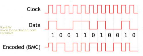
As shown from this diagram the encoder output changes polarity at each positive clock edge, but it also changes polarity at the negative clock edge IF THE DATA IS a 1. There is a requirement that there be a few zeros in any frame to enable the detector to lock. It works well if the signal is continuous or a burst of repetitive transmissions. A 3 KHz clock will give a signal that will pass through a telephone quality audio pass band, through a simple radio system. A Micromite may cut this speed. To decode the data the received analog �Audio� signal must be squared up or �sliced� back into a digital signal. This requires a comparator (LM311 $1.65). Then an edge generator to create short pulses on both the rising and falling input edges (one quad nand gate 74HC00 or 4011 $0.95) that will trigger a monostable (LM555 or 4047 $1.25) whose period is about three quarters of the data rate, plus a data latch (4027 $0.95) and a few resistors and small capacitors. Possibly the monostable (timing or delay) and latch functions can be performed using a Micromite digital input with an edge interrupt starting a time delay, OK for slow data rates. The trailing edge of the monostable becomes the decoded data clock. Data is detected as a 1 if there is an edge pulse detected while the monostable is still high. Due to zeros within the signal code the monostable will lock to the correct edges to decode correctly. I will draw a circuit and timing diagram if anyone is interested and have specified here CMOS for low voltage operation but would prefer HC types at 5 volts. Unique data patterns used when only a small number of control codes must be communicated will easily be detected when shifted into a register, perhaps a Micromite text string can be shifted and compared. If more complex data is involved then generation and detection of unique data headers must be used to designate the beginning of data frames. For instance for Timecode the header was �0011111111111101�, which pattern did not occur in the data and also indicated if the data was being received forward or backwards, i.e. spooling forward or back. History: - SMPTE (Society of Motion Picture and Television Engineers) Timecode can be read forward and backwards over a large speed range when tape was spooled. It enables the location of any desired frame within a recording and the locking of recorders together to record or play in sync. Separate recorders may be used to record the video from multiple cameras together with a multi-track audio recorder that then must be all replayed sync locked together to edit a program. Initially Timecode was recorded as an extra audio signal that was �clocked� at 4 KHz. This giving 80 bits in 20 milliseconds or 1 frame (for PAL) and locked to video sync. I designed and built Timecode readers that were used in Video Editing equipment and economic displays for a �Time of Day� clock distribution system. Keith W. |
||||
| OA47 Guru Joined: 11/04/2012 Location: AustraliaPosts: 1050 |
So I have given the Kansas City Tape Interface protocol a bit of a go. Have got some results....... Here is a screen shot of the demodulated sampled word generated by the micromite, transmitted over the UHF radio and analysed by the maximite. 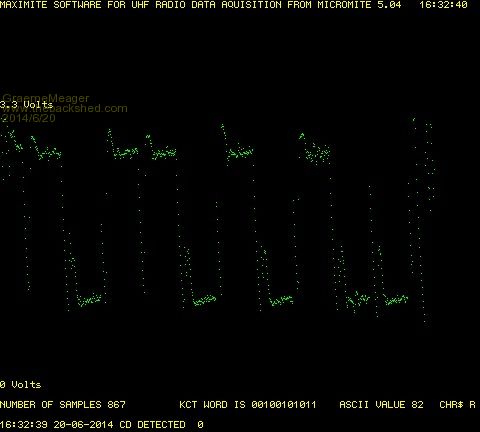
The bits are fairly well defined and although it is not very scientific, I am using this code to decifer the bits: Sub GETWORD 'READ AVERAGE OF 5 SAMPLES FOR EACH BIT AND CONVERT TO BINARY
For WW=20 To 800 Step 75 AVSMPL=(KCTWORD(WW)+KCTWORD(WW+1)+KCTWORD(WW+2)+KCTWORD(WW+3 )+KCTWORD(WW+4))/5 If AVSMPL >1.50 Then KCTBIT$="0" Else KCTBIT$="1" KCTWORD$=KCTWORD$+KCTBIT$ Next WW Print @(180,400)"KCT WORD IS ";KCTWORD$ I am aware that I will have variations in signal strength and timing so I was wondering if anyone could advise on more accurate methods of coding. |
||||
| TassyJim Guru Joined: 07/08/2011 Location: AustraliaPosts: 6538 |
You have made good progress! I still intend to play with the IR commands, reduced in frequency to suit audio. When I have time, that is... Over FM, the signal strength does not affect the amplitude of the audio. It is only when the signal strength is low and there is noise on the audio that you may have problems. It looks like there is a bit of overshoot so a small capacitor across the audio might help. Another way of decoding is to look for the start transition then wait until you are in the middle of the timing cycle to do a read. I will have to read up on the Kansas City protocol. Jim VK7JH MMedit |
||||
| OA47 Guru Joined: 11/04/2012 Location: AustraliaPosts: 1050 |
I have been using a 180p cap as it gave the best compromise of waveform shape and symmetry. I did a long term test using the format and got near 100% error free over 400 packets. The horizontal scale shows the relative sample points across the data bits. The first bit is short as I am relying on the CD line to set the interrupt and there is a time delay for this to happen. By default for KCTS the first bit must always be a 0. Not sure why but there was a bit of drift in the amplitude/magnitude of the audio output. I have managed to overcome this by using the first sample as the voltage reference for the maximum height of the waveform. 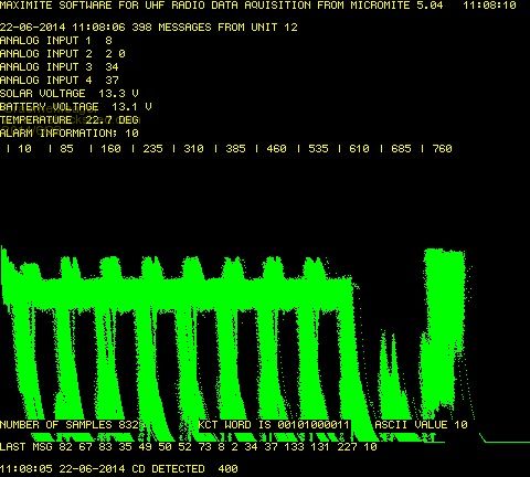
Next step conversation between the Micromites and Maximite..... |
||||
| greybeard Senior Member Joined: 04/01/2010 Location: AustraliaPosts: 181 |
Looking good Graeme |
||||
| The Back Shed's forum code is written, and hosted, in Australia. | © JAQ Software 2026 |
