
|
|
Forum Index : Microcontroller and PC projects : Micromite beginner stuck
| Page 1 of 2 |
|||||
| Author | Message | ||||
Herry Senior Member Joined: 31/05/2014 Location: AustraliaPosts: 261 |
Hello Apologies if this is not the right place. Have just bought Micromite from Silicon Chip, and wired up per basic instructions, using a polulu USB/Serial converter. Proved that is OK by looping TX and RX. No MMBasic announcement or command prompt. Current draw at approx. 3 volts just 4 mA. Any ideas? Possibly a blank PIC and not pre-programmed at all? Senior?! ĀWhatever it says, I'm a complete and utter beginner... |
||||
| Goeytex Regular Member Joined: 12/05/2014 Location: United StatesPosts: 74 |
Hi Herry, I assume that you are using TeraTerm. 1. You will need to set the correct port & baud rate in TeraTem. Open TeraTem then click on > Setup > Serial Port. Select the correct port for your adapter. Then set the baud rate to 38400. The serial port can be any where from Com1 to Com16 or higher. If you are unsure then look in Device Manager under "Ports". 2. Make sure that the RX & Tx from the Serial Adaper to the Micromite are not reversed. I have seen some adapters where the RX pin marked on the adapter is actually the output. It is highly unlikely that you received a blank chip. Let us know how it goes. Bill |
||||
| Herry Senior Member Joined: 31/05/2014 Location: AustraliaPosts: 261 |
Hi Bill Thanks for your speedy reply. Is this the OK place for this thread then? Yes I am using Tera Term and I've set up the port no and baud etc. stuff. I have quadruple checked the TX and RX. Perhaps I should try a swap? Senior?! ĀWhatever it says, I'm a complete and utter beginner... |
||||
| robert.rozee Guru Joined: 31/12/2012 Location: New ZealandPosts: 2527 |
with Rx and Tx connected together, check the voltage to ground. it should be either 3.3v or 5v. as keys are pressed, it should 'flicker'. if it is -12v, you have a usb to serial bridge with built-in line drivers. this is not suitable. if it is 0v, then the signal polarity is inverted and you need to add in inverters (or find the software for your bridge to change the polarity of Rx and Tx). if it is 5v, you need to add 1k resistors in series with both lines - strictly speaking you only need a resistor in series with the line running to the Rx pin on the micromite, but it does no harm having resistors in series with both. if still no luck, try swapping round Rx and Tx. even if correctly marked, it is easy enough to get confused and reverse them. please do report back your findings! rob :-) |
||||
| Herry Senior Member Joined: 31/05/2014 Location: AustraliaPosts: 261 |
Thanks Rob. With TX/RX looped, voltage from loop to earth is 3.35. Does not flicker when keys pressed. However, characters on keyboard are echoed to screen so at least know that port and driver are OK. Tired swapping no difference. Maybe its a setting? *Correction edit* Can now see slight flicker on the fluke when key held down and repeating Senior?! ĀWhatever it says, I'm a complete and utter beginner... |
||||
| robert.rozee Guru Joined: 31/12/2012 Location: New ZealandPosts: 2527 |
that is a good sign... lets look at the micromite itself again. 4mA strikes me as a little bit low, as if the chip is either un-programmed or being held in reset or some such. have you got it wired up correctly; are you 100% sure? GROUND: pins 8, 19, and 27 Vcc: pins 1, 13, and 28 (pin 1 may be tied to Vcc via a 10k resistor) Is the capacitor connected between ground and pin 20? Pin 20 should ONLY connect to the +ve terminal of the capacitor, and to nothing else. Pin 20 should NEVER be connected to Vcc. i believe you should be able to measure something like 1.8v across the capacitor. if a micromite is functional and programmed correctly, one test is to connect an LED between pins 11 and 13 (longest lead to 13). when power is applied the LED should briefly flicker brightly as the 'signon' message is transmitted by the micromite. all you need is power for this test, no serial connection. rob :-) |
||||
Grogster Admin Group Joined: 31/12/2012 Location: New ZealandPosts: 9975 |
Excellent idea and suggestion with the LED, Rob. Nice one.  Smoke makes things work. When the smoke gets out, it stops! |
||||
| paceman Guru Joined: 07/10/2011 Location: AustraliaPosts: 1329 |
Yes that's a beauty Rob - about as simple and quick as it gets! |
||||
| Herry Senior Member Joined: 31/05/2014 Location: AustraliaPosts: 261 |
Hi chaps Monday a.m. (very!) early and back in saddle. Rob, to answer you... 4mA strikes me as a little bit low, as if the chip is either un-programmed or being held in reset or some such. have you got it wired up correctly; are you 100% sure? ***unprogrammed exactly what I suspect. GROUND: pins 8, 19, and 27 Vcc: pins 1, 13, and 28 ***checked OK Is the capacitor connected between ground and pin 20? Pin 20 should ONLY connect to the +ve terminal of the capacitor, and to nothing else. Pin 20 should NEVER be connected to Vcc. ***checked OK i believe you should be able to measure something like 1.8v across the capacitor. ***not there if a micromite is functional and programmed correctly, one test is to connect an LED between pins 11 and 13 (longest lead to 13). when power is applied the LED should briefly flicker brightly as the 'signon' message is transmitted by the micromite. all you need is power for this test, no serial connection. ***tried. No flicker I do feel that all tests point to me getting non-programmed chip in error. I'll await the response of the supplier today Thanks all Senior?! ĀWhatever it says, I'm a complete and utter beginner... |
||||
| WhiteWizzard Guru Joined: 05/04/2013 Location: United KingdomPosts: 2991 |
Do you have another capacitor to try as if the one you are using is faulty in some way then you won't see 1.8v, you won't get the expected 20mA (approx) current draw, AND you won't get the LED flicker from the start up message! You are experiencing all the signs of a possible cap failure. My money is also on a 'faulty' PIC BUT it is worth trying the cap first if possible. By the way, what cap are you trying? 47uF rant or 10uF multilayer ceramic (or something else?) WW |
||||
BobD Guru Joined: 07/12/2011 Location: AustraliaPosts: 935 |
sorry Phil, but I just had to have a laugh at a 47uF rant  |
||||
| WhiteWizzard Guru Joined: 05/04/2013 Location: United KingdomPosts: 2991 |
for once Bill Gates' spelling checker may have got it correct!! |
||||
| Grogster Admin Group Joined: 31/12/2012 Location: New ZealandPosts: 9975 |
Well, there was a-lot of discussion on suitable caps and values on another thread, so you could call that a rant of sorts!!!
Back on topic, yes I also agree with WW here - with a crook cap or the wrong cap(DON'T use a bog-standard aluminium electro!), I think that if that is not doing it's thing correctly, then the PIC32 core will not start or run properly, and therefore, won't draw the expected current or output any serial, or respond to your attempts to wake it up. If you got your chip from Silicon Chip magazine, they were also supplying the cap, so I would expect that this should be correct and OK, but as WW says: swap the cap for another one if you have one, for the purposes of testing. Smoke makes things work. When the smoke gets out, it stops! |
||||
bigmik Guru Joined: 20/06/2011 Location: AustraliaPosts: 2981 |
Gday Herry, Welcome to uMite central.. 
OK! Firstly what voltage do you see there? I would be very surprised that it is exactly zero.. This is the obvious point of there being some problem.. I just checked with one of my chips and I see around 1.8v with BOTH a programmed and a BLANK Pic chip across C1 If you are seeing nothing as in 0v then I suspect a wiring problem.. Check that C1 is connected (using a meter), +ve (the side with the line if using a Tantalum) to pin 20 of the pic32 and -ve side to pin 19 of the PIC32.. Also check that there is no short across the capacitor.. Now you may be aware of pin numbering but just to be sure this picture shows the pinout clearly. 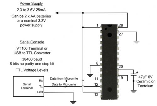
Your Avatar says you are in AUSTRALIA, are you in Melbourne? I am happy to assist if you are local enough. Regards, Mick Mick's uMite Stuff can be found >>> HERE (Kindly hosted by Dontronics) <<< |
||||
OA47 Guru Joined: 11/04/2012 Location: AustraliaPosts: 1050 |
Herry, just one question if I may do you have a 10k ohm resistor from pin 1 to 3.3V or do you have a direct link? |
||||
| Goeytex Regular Member Joined: 12/05/2014 Location: United StatesPosts: 74 |
Is the circuit on a breadboard? Or soldered up ? I might suggest taking closeup photo of the breadboard setup and posting the image so that we can take a look. While it it tempting to think that the chip is blank or defective, I find those the least likely possibilities. I have a blank chip here and when connected per the diagram the voltage on Pin20 is 1.8V. A reading of zero volts indicates either a supply problem or possibly a shorted cap. Remove the cap and measure again. It should also be about 1.8V. If still zero volts. Then take the following measurements. Measure directly across the Pins with the Gnd lead on the first Pin and the Red lead on the second pin. Do not attach the meter gnd lead to the gnd rail. 1) With the Cap removed & power connected .... Measure from: Pin 8 to Pin 1 Pin 8 to Pin 28 Pin 8 to Pin 13 Pin 27 to Pin 1 Pin 27 to Pin 28 Pin 27 to Pin 13 Pin 19 to Pin 1 Pin 19 to Pin 28 Pin 19 to Pin 13 These should ALL read 3.3V. If not then check wiring until corrected. Once corrected .... or if all good then ... 2) Connect the cap between Pins 19 & 20 with the + side of the cap on Pin 20 Take the readings again. All should still read 3.3V 3) Read directly across Pins 19 & 20. It should be 1.8V Make sure that breadboard rails are jumpered properly. Some breadboards have segmented rails ( breaks between the red lines). These breaks need to be jumpered for the rail to extend all the way across the breadboard. Make sure that the GND on the Serial adapter is tied to the GND gnd on breadboard/Micromite chip. If all of this does not lead to a solution, then the chip is likely blown. ============================================================ = The only defective PICs I have ever had were "defective" because I accidentally applied either too much voltage or accidentally applied reverse voltage. This usually resulted in the chip drawing excessive current when proper power was applied. Bill |
||||
| Herry Senior Member Joined: 31/05/2014 Location: AustraliaPosts: 261 |
Well, egg on face department speaking! Thanks chaps for all the help. I received from Silicon Chip magazine a replacement chip and...that didn't work either! By now thoroughly bamboozled, I tried replacing everything, even the patch leads one by one. When it got to the project board BINGO! It was the *&$# board all the time! Can't remember where I bought that particular board. Wish I could! So all OK now. Thanks again all of you for detailed and great help help! Duh department signing off and looking for the 'RESOLVED' tag! ...which I can't find! *** Alan Senior?! ĀWhatever it says, I'm a complete and utter beginner... |
||||
| Grogster Admin Group Joined: 31/12/2012 Location: New ZealandPosts: 9975 |
Glad you got it sorted. Did you try the original chip to see if it now works? EDIT: BTW, as far as your eggy face - don't worry. I am sure you have leart from all this, and we all here love a good mystery!!!!(if that is not too presumptuous of me to say on behalf of everyone else!) Thanks for being HONEST, and posting back what REALLY happened.(by that I mean many would not - they might say something like "New chip is working fine" kind of thing.)Smoke makes things work. When the smoke gets out, it stops! |
||||
| MicroBlocks Guru Joined: 12/05/2012 Location: ThailandPosts: 2209 |
I often found that it was not really the board that causes the problems but it were the wires. The cheaper ones have very thin pins are do not really connect very well. If they are to big they can bend the metal strips inside the breadboard and also cause problems. Finding the right ones for a board can be difficult, a lot of trial and error. Microblocks. Build with logic. |
||||
| Herry Senior Member Joined: 31/05/2014 Location: AustraliaPosts: 261 |
Yes, I did try the original chip and that worked too, so I'll purchase the new one (not send the old one back as invited). The problem with that particular breadboard was that the contact strips were too far down into the plastic, so the pins of the Micromite did not reach them. Thanks again all! No doubt I'll be back! Senior?! ĀWhatever it says, I'm a complete and utter beginner... |
||||
| Page 1 of 2 |
|||||
| The Back Shed's forum code is written, and hosted, in Australia. | © JAQ Software 2026 |
