
|
|
Forum Index : Microcontroller and PC projects : Problem with TFT-Maximite display
| Author | Message | ||||
| raketenbuggy Newbie Joined: 08/02/2014 Location: GermanyPosts: 21 |
I have a TFT-Maximite rev. 1.3 bought at segor.de. The Maximite itself works fine, but I have a problem with the display: If the supply voltage is slightly below 5V (at about 4.5 to 4.6 V) everything is ok. If it is about 5V the screen content is jumping erratically (every 0.5 to 5 sec.) down by exactly one line. segor has a page that describes a bugfix for some sort of image jittering (http://www.segor.de/#/bauteilesaetze-a-module/bauteilesaetz e/ct-tft-maximite). According to Carsten Meyer this bugfix should solve my problem. He was right, it worked, but unfortunatelly not as I hoped it would. The screen content is not jumping anymore one line down erratically, now it is shifted permanently one line down so that the last line is not displayed. 
I tried to contact Mr. Meyer again but didn't get any answer until now. I don't know much about video signals, but I guess that the slope of the sync-signals is too slow now so that the synchronisation is not working correctly anymore. I replaced the additional 1k resitor with a small potentiometer and after some fiddling with the two potentiometers I got a stable and complete image. It's working now, but I still have some questions: - Is this a common problem or am I the only one affected? - Is my guess with the additional resistor right, is it messing with the signal slope? - Would it be better to reduce C6 instead of adding a resistor? - Is this a problem of the display (manufaturing tolerances) or a problem of the controlling circuit (the TFT-maximite)? Michael |
||||
| Geoffg Guru Joined: 06/06/2011 Location: AustraliaPosts: 3362 |
It would help if we could use the link that you posted but it leads to an error page. If you want to post a link on the Back Shed you should use the link button (fourth button from the left in the edit toolbar). Geoff Geoff Graham - http://geoffg.net |
||||
donmck Guru Joined: 09/06/2011 Location: AustraliaPosts: 1314 |
there you go: http://www.segor.de/#/bauteilesaetze-a-module/bauteilesaetze /ct-tft-maximite Cheers Don... https://www.dontronics.com |
||||
bigmik Guru Joined: 20/06/2011 Location: AustraliaPosts: 2981 |
Hi Geoff, It is the old `Back SHed lets add random spaces' problem Here is the link Michael was referring to: Link I hope you are enjoying your holidays. Mick EDIT*** Bugger you McKenzie.. Beat me again.. 
Mik Mick's uMite Stuff can be found >>> HERE (Kindly hosted by Dontronics) <<< |
||||
| donmck Guru Joined: 09/06/2011 Location: AustraliaPosts: 1314 |
 https://www.dontronics.com |
||||
| raketenbuggy Newbie Joined: 08/02/2014 Location: GermanyPosts: 21 |
Hi folks, sorry for the trouble with the link, I forgot about the spacing-problem (should have used the link-button). I guess it was too late last night. 
Thanks to everybody who corrected the broken link! Michael EDIT: I found a new thread in the german heise-forum concerning display-troubles. It seems that the same problem is also occuring with the latest board revision segor is selling. If I got it right, the "bugfix-circuit" is used there as standard. The thread: http://www.heise.de/forum/c-t-Hacks/Heft-Projekte/Artikelfor en-Heft-4-2013/Color-Maximite-2/Maximite-1-4-Displayausgabe- deutlich-schlechter-als-bei-1-3/posting-2140421/show/ The schematic: https://github.com/heise/MAXIMITE/blob/master/TFT%20MM%20Sch altplan%201_4.pdf?raw=true |
||||
| Geoffg Guru Joined: 06/06/2011 Location: AustraliaPosts: 3362 |
Michael The webpage will not open in Google translate and anyway seems to be just advertising for the TFT Maximite - so we have no idea what the "fix" is. You should post the information directly rather than just posting links. Geoff Geoff Graham - http://geoffg.net |
||||
| Geoffg Guru Joined: 06/06/2011 Location: AustraliaPosts: 3362 |
After a bit of searching I found the "bug fix". This is Google's poor translation of it: This is a hardware issue caused by the circuit (designed by Carsten Meyer) used to delay the sync pulse. There is not much that can be done to improve the issue because the circuit used is so simple - as you say, it is "messing with the signal slope". So your trick of replacing the resistor with a trimpot is probably the best solution but the exact fix will vary with different LCDs. Geoff Geoff Graham - http://geoffg.net |
||||
| robert.rozee Guru Joined: 31/12/2012 Location: New ZealandPosts: 2528 |
the sync pulse 'delay' circuit looks all wrong. as far as i can tell, this is what is implemented, which actually does several things: 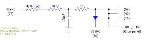
firstly, it messes with the maximite's operation. normally pins 14, 47, 69, and 77 are linked together, and provide the horizontal sync (HSYNC) output to the VGA monitor. the circuit breaks the link from pin 77 and (1) inserts a delay, and, (2) gates the signal feeding back into pins 14, 47, and 69 with the vertical sync (VSINC) signal. secondly, and more importantly for the TFT panel, is that the delayed and gated pulse, now called START_HSYNC is fed into the DE input of the panel. DE is 'data enable', and is a signal that is required to be active only while valid video data is present on the Rn,Gn,Bn lines. as i recall from testing work i did with these panels a few years back (covered by NDA) the DE line needs to go active some number of HSYNC pulses after each VSYNC pulse. the exact number is specified in the data sheet for the panel, and varies by model. it may also require to be active only during the portion of the line that contains valid pixel data. without the DE signal, the panel will display nothing, as i recall. this was, remember, a few years back, and so i am a little fuzzy. i was doing the hardware, another engineer handling the software. we derived out DE signal internally to our controlling device and adjusted it for each panel being tested. the first problem that i can see with this circuit is that of delaying the signal that is sent back into the 32MX695. in the above diagram, pins 14,47, and 69 should be connected to HSYNC rather than START_HLINE. i guess Geoff is the best person to comment on the effect of this. the second problem is that the DE generated is just, well, all wrong. really it should be generated from a counter running off HSYNC, with the counter reset by VSYNC; the output then being active when the count is > n, where n is an adjustable line number. it may also require to be further gated on and off during each line. these may well be functions that MMbasic firmware could best generate itself, or certainly assist with. my suspicion is that the designer wished to be able to use MMbasic unaltered. rob :-) |
||||
| Geoffg Guru Joined: 06/06/2011 Location: AustraliaPosts: 3362 |
I don't have all the documentation with me but from memory the LCD panel needed the start of the video to be delayed compared to normal VGA. Pins 14, 47 and 69 are the framing inputs to the three SPI channels (red/blue/green) and they prevent the SPI channels from starting while they are low. By delaying the rising edge of this signal the start of the video was delayed. There are probably many more robust ways of achieving this but we have the benefit of hindsight. At the time using a simple RC delay probably seemed "good enough". Geoff Geoff Graham - http://geoffg.net |
||||
| robert.rozee Guru Joined: 31/12/2012 Location: New ZealandPosts: 2528 |
it certainly provides some clues about why behaviour can be dependant on supply voltage - if the 3v3 line is marginal at 5v supply coming into the board, then the 0/1 threshold levels will change with supply and hence the timing. plus the delay circuitry assumes that both 32MX695 and LCD panel both have exactly the same thresholds. just a theory. off the top of my head, the 32MX695 has four SPI channels, yes? so one could switch to an alternative approach: use the 4th SPI channel to generate DE from a 4th plane of video data. the data for this channel could always come from flash, or at least from a single line of data held in RAM - there would be no need to increment any line counter as every 'line' would be identical. then implement the vertical blanking part of DE purely in the MMbasic firmware - simply turn the 4th channel on/off at the appropriate starting and ending video line numbers (using the line counter used for the other 3 R/G/B planes). as for the need to delay the R/G/B data, increase the length (in pixels) of the video lines and always make the first n pixels black. or accept a lesser horizontal number of pixels without needing to introduce a delay. it does seem that the role of the DE signal is being a little underestimated by all - it defines the 'window' of video data that put up on the LCD panel, and so is quite vital. would this work? rob :-) |
||||
| raketenbuggy Newbie Joined: 08/02/2014 Location: GermanyPosts: 21 |
I'm sorry for causing trouble with my links again! I didn't post the information directly because I didn't want to run into copyright issues. Besides I thought that this issue is already known and you knew what Carsten Meyer is doing. Sorry again! Thanks for your evaluation. I'm happy that my guess was not completely wrong. 
I did some meassurments: - Between 1000 and 350 Ohms the last line is allways missing but theres no jitter. - Between 350 and 20 Ohms it is possible to get a clean image by adjusting the h-sync potentiometer, but if the supply voltage is changing the last line can vanish or jittering may occure, so it can be necessary to readjust h-sync. - Below 20 Ohms the image is jittering. At around 50 Ohms I got a permanently clean image, even for different supply voltages (down to 4.5V and below) without readjusting h-sync. So 1k Ohm is definitly too much, at least for my TFT-Maximite. And (with a little bit of tweaking) it's working fine, so it can't be that bad. The simple solutions are often the best. And besides, afterwards you always know better.
Michael |
||||
f1fco Senior Member Joined: 18/03/2012 Location: FrancePosts: 155 |
I receive my TFT Maximite 2 weeks ago and I start to play with it... on my board, version 1.4, the modification is ready made (R23) as on the schematics here : https://github.com/heise/MAXIMITE/blob/master/TFT%20MM%20Sch altplan%201_4.pdf I receive this message from Segor Electronics : "thank you for your information. We currently do not recommend to use Version 4.5 of MMBasic, some customer reported display positioning problems with this version. This issue is currently under investigation by Mr. Meyer and Geoff. If your display does not show an exact positioning please downgrade to Version 4.4b." another problem : the USB DRIVER for Maximite (download on the site of Geoff) http://geoffg.net/maximite.html for Silicon_Chip_USB dont work for my TFT Maximite and PC unde Windows 7 64 bits where to find the right driver ? Pierre 73s de F1FCO |
||||
BobD Guru Joined: 07/12/2011 Location: AustraliaPosts: 935 |
It doesn't work for one of my machines under Win 7, win 8, and win 8.1 but it works OK on my laptop running both win 7 32 bit and 64 bit (dual booting). It has been like that since the Maximite came out. |
||||
| raketenbuggy Newbie Joined: 08/02/2014 Location: GermanyPosts: 21 |
The driver which can be downloaded from geoff is not intended to run under somthing newer than Vista. I don't have win7, but I heard that it's a bit difficult (up to nearly impossible) to use the mchpcdc-Driver under win7 and newer. Maybe there's an actual version avaiable on the microchip website. @ Pierre: You didn't write it explicitly but I think you're having similar problems with your display (image shaking). If this is right, how bad is the problem on your side? Is your image jumping also for one line up and down or is it shifted permanently? Replacing R23 with a 500Ohm potentiometer is working faily well for me. After updating the firmware from V4.4 to V4.5 I had to readjust both potentiometers (it's a fiddly work because one affects the other), but finally (after about 1/4h) I got a stable image. But my TFT-Maximite is the "old" one, board rev. 1.3. Michael |
||||
| f1fco Senior Member Joined: 18/03/2012 Location: FrancePosts: 155 |
hello Michael, thank you for message if I understand, no issue (today) with Windows 7 !!! waiting for windows "nine"... R23 is 1Kohms on my board rev 1.4 I will try to replace it with a 500ohms pot. actually with 1K, image (on TFT 5") is stable I repeate the message of Segor Electronics about version 4.5 because with the "AUTORUN.BAS" file test, I cannot access to the first line (10 - COLRDEMO.BAS) I will load version 4.4 to try again my major and big problem is the USB driver... I cannot use MMedit, or MMide to edit programms on my PC (easyest than the small screen of TFT Maximite) Pierre 73s de F1FCO |
||||
| Geoffg Guru Joined: 06/06/2011 Location: AustraliaPosts: 3362 |
The Silicon Chip USB device driver works fine with both 32-bit and 64-bit versions of Windows 7. Hundreds of people are running the drivers on Win7 with no problems at all. Geoff Geoff Graham - http://geoffg.net |
||||
TassyJim Guru Joined: 07/08/2011 Location: AustraliaPosts: 6538 |
The driver also works well with Windows 8 and 8.1 If you are having problems installing on W7, perhaps the security settings are too tight. With Windows 8 and 8.1 you do need to find out how to install un-certified drivers. Doing a Google search will give you a number of choices of instructions. Jim VK7JH MMedit |
||||
| raketenbuggy Newbie Joined: 08/02/2014 Location: GermanyPosts: 21 |
@ Pierre: The driver can run under win7, but there are cases when it does not. And if it does not there seems to be no solution that always works (see below). If your display is working fine (if you see the whole image and no lines or colums are cut off temporary or permanently) you don't have to replace the resistor. @ Geoff & Jim: A friend of mine has win7 and he tried to get the driver working but without success. He questioned google and found several people with the same problem, but no universal solution. Some wrote that you have to edit the inf-file, but for him it didn't work. IIRC the installation ran through but the TFT-Maximte was not recognised when connected. So if you have some hints please let us know. Michael |
||||
| The Back Shed's forum code is written, and hosted, in Australia. | © JAQ Software 2026 |
