
|
|
Forum Index : Microcontroller and PC projects : [MicroMite]AD9850 Controller Source Code
| Page 1 of 2 |
|||||
| Author | Message | ||||
| G8JCF Guru Joined: 15/05/2014 Location: United KingdomPosts: 676 |
I've had a few requests for the source of my AD9850 Controller code which works with the cheap Chinese eBay boards - it will in fact work with any AD9850 chip/module, eg NJQRP DDS30 but you will need to change DivConst to suit the Xtal oscillator used on the module. So here it is, warts and all 'AD9850 VFO Controller V9 '(c)Peter Carnegie - GM8JCF - 2014 'eBay AD9850 Modules use 125,000,000 Hz Clocks 'AD9850 Fout= (Δ Phase � CLKIN)/2^32 where Fout=32 bit tuning word 'TuningWord= Fout * 2^32 / CLKIN = Fout * (2^32/125,000,000) '2^32/125,000,000 = 34.359738368 - VB6 Double Precision 'Using Integer only arithmetic, multiply by 1,000,000 'DivConst= 34359738 'We then divide the result of TuningWord=DivConst * Fout by 1,000,000 'Initialise the BCD Library InitBCDLib DIM DivConst(7) 'Load it up in BCD LoadBCD DivConst(0),"34359738" 'Cur Freq in BCD DIM CurFreq(7) 'Load it up in BCD LoadBCD CurFreq(0),"10000000" 'Define DDS Control pins FQUD=18 SData=17 WCLK=16 'Initialise the LCD Display DispLen=16 '26=D7, 25=D6, 24=d5, 23=d4 '22=RS, 21=EN LCD init 26,25,24,23,22,21 'Rotary Encoder Input pins - see page 22 uMite User Manual DIM RA,RB RA=2 RB=3 SETPIN RB, Din SETPIN RA, INTH, RInt 'Variable incremented/decremented by the Interrupt handling 'routine for the Rotary Encoder DIM Value,LastValue 'Raw Tuning Word, ie scaled by 1E6 DIM RawTWord(7) 'Tuning Word scaled back to real world units, ie divide by 1E6 DIM TWord(7) 'Index of which Step size is in force DIM CurStepIndex 'Startup with 100Hz tuning steps CurStepIndex=2 'Current Step in TWord units DIM CurStepTW(7) 'Array of Possible Step Sizes in Hz DIM StepHz(4) StepHz(0)=1 StepHz(1)=10 StepHz(2)=100 StepHz(3)=1000 'What to Add/Subtract from the Scaled tuning Word 'for each Encoder Up/Down DIM StepTWord$(4) Length 24 'These TuningWord sizes were calculated using Double precision arithmetic 'in VB6 StepTWord$(0)="34359738" '1Hz Step StepTWord$(1)="343597384" '10Hz StepTWord$(2)="3435973837" '100Hz 3435973836.8 StepTWord$(3)="34359738368" '1000Hz 'Load the CurStepTW with the startup Step in TW LoadBCD CurStepTW(0),StepTWord$(CurStepIndex) 'Calculate Starting TuningWord CopyBCD DivConst(0),BCDA(0) CopyBCD CurFreq(0),BCDB(0) 'Calculate the Tuning Word, this one is * 1E6 MulAB2C 'Save the RawTWord CopyBCD BCDC(0), RawTWord(0) 'Start with clean BCD Registers ClrBCD(BCDA(0)) ClrBCD(BCDB(0)) ClrBCD(BCDC(0),15) 'Go do Main Loop Main END SUB Main 'General purpose String used in Main Loop LOCAL D$(1) length 24 LOCAL I,L,Cy 'Flag when rotary encoder has moved. LOCAL Change D$(1)="GM8JCF" LCD 1, C16, D$(1) DispFreq 'Initialise the I/O & DDS chip InitDDS 'Save Power CPU 5 'Do for ever ! DO Change=Value-LastValue Value=LastValue 'Any movement ? IF Change<>0 THEN 'We need all the speed we can get for the calculations CPU 48 'If encoder is turning ANTI-clockwise, Decrement 'If encoder is turning CLOCKwise, Increment IF Change<0 THEN DecCurFreq(StepHz(CurStepIndex)) ELSE IncCurFreq(StepHz(CurStepIndex)) ENDIF 'Calculate the change to the Tuning Word 'If ANTI-clockwise then decrement TuningWORD 'If CLOCKwise then incrementg TuningWORD IF Change<0 THEN 'Decrement Cy=0 FOR I=0 TO 7 IF RawTword(I)>=CurStepTW(I)+Cy THEN RawTword(I)=RawTword(I)-CurStepTW(I) - Cy Cy=0 ELSE RawTword(I)=RawTword(I)+1000 - CurStepTW(I) - Cy Cy=1 ENDIF NEXT I ELSE 'Increment Cy=0 FOR I=0 TO 7 RawTword(I)=RawTword(I) + CurStepTW(I) + Cy IF RawTword(I)>999 THEN Cy=RawTword(I)\1000 RawTword(I)=RawTword(I) MOD 1000 ELSE Cy=0 ENDIF NEXT I ENDIF 'Save the New Tuning Word for next time FOR I=0 TO 7 BCDC(I)=RawTword(I) NEXT I 'Round to the nearest 1,000,000 'ie Add 500,000, then chop off the last 6 digits Cy=500 FOR I=1 TO 3 BCDC(I)=BCDC(I)+Cy IF BCDC(I)<1000 THEN EXIT FOR ELSE Cy=BCDC(I)\1000 BCDC(I)=BCDC(I) MOD 1000 ENDIF NEXT I 'And make the Actual DDS Tuning Word, ie scale down by 1E6 'For BCD that just means removing the last 6 digits FOR I=2 TO 7 BCDA(I-2)=BCDC(I) NEXT I BCDA(6)=0:BCDA(7)=0 'Convert BCD to UINT32 BCDA2Bin SendDDSData DispFreq 'Reset change flag for next iteration Change=0 'Slowdown the CPU to save power CPU 5 ENDIF 'Go check again LOOP END SUB END 'Interrupt Routine 'Here when the Rotary encoder moves RInt: IF PIN(RB)=1 THEN 'Clockwise rotation Value=Value+1 ELSE 'Anti-Clockwise rotation Value=Value-1 ENDIF IRETURN '========================================================= 'Increment CurFreq() by Inc ' ' SUB IncCurFreq(Inc) LOCAL I,Cy Cy=Inc FOR I=0 TO 2 CurFreq(I)=CurFreq(I) + Cy IF CurFreq(I)<1000 THEN EXIT FOR ELSE Cy=CurFreq(I)\1000 CurFreq(I)=CurFreq(I) MOD 1000 ENDIF NEXT I END SUB '========================================================= 'Decrement CurFreq() by Dec ' ' SUB DecCurFreq(Dec) DIM I, Cy Cy=Dec FOR I=0 TO 2 IF CurFreq(I)>=Cy THEN CurFreq(I)=CurFreq(I)-Cy EXIT FOR ENDIF CurFreq(I)=CurFreq(I)+1000 - Cy Cy=1 NEXT I END SUB '========================================================= 'Returns a string representing the BCD Digits from CurFreq() 'eg if CurFreq(0)=123, CurFreq(1)=456,CurFreq(2)=789, then 'CurFreq2ASC$ will return "789456123" ' FUNCTION CurFreq2Asc$() LOCAL I,J,A$(1) Length BCDSize*3,B$(1) Length BCDSize*3 'Frequency is 8 digits long , eg 30,000,000 FOR I=2 TO 0 STEP -1 'Find First non Zero Triplet IF CurFreq(I)<>0 THEN FOR J=I TO 0 STEP -1 B$(1)=B$(1)+STR$(CurFreq(J),3,0,"0") NEXT J 'Now Remove any leading Zeroes FOR J=1 TO 3 IF PEEK(VAR B$(1),J)<>&H30 THEN B$(1)=MID$(B$(1),J) EXIT FOR ENDIF NEXT J EXIT FOR ENDIF NEXT I CurFreq2Asc$=B$(1) END FUNCTION '========================================================= ' ' ' SUB InitDDS SETPIN FQUD, DOUT : PIN(FQUD)=0 SETPIN SData, DOUT : PIN(SData)=0 SETPIN WCLK, Dout : PIN(WCLK)=0 SetFreq END SUB '========================================================= ' 'Fundamental equation for DDS 'Tuningword = FrequencyDesired * (AccumulatorBits / ClockIn) 'For an AD9850, TuningWord = F * ( (2^32) / ClkIn ) ' SUB SetFreq LOCAL I,J,TWord(7) FOR I=0 TO 7 BCDA(I)=CurFreq(I) NEXT I FOR I=0 TO 7 BCDB(I)=DivConst(I) NEXT I 'Calc the Tuning Word MulAB2C 'Save this Long Tuning Word FOR I=0 TO 7 RawTWord(I)=BCDC(I) NEXT I 'Div by 1E6 J=0 ClrBCD(BCDA(0)) FOR I=2 TO 7 BCDA(J)=BCDC(I) J=J+1 NEXT I 'Convert BCDA() to 8 hex digits, ie 32 bits BCDA2Bin 'Tuning Word is now in BCDC() 'Send it to out SendDDSData END SUB '========================================================= ' 'Tuning Word to be sent to the DDS must be in BCDC() ' ' SUB SendDDSData LOCAL I BCDC(4)=0 PIN(FQUD)=0 'Make sure FQUD is Low PIN(WCLK)=0 'Clock pin Low PIN(Sdata)=0 'Data Pin Low 'Send the Tuning Word and Control bytes to the AD9850 FOR I=0 TO 4 Send8Bits(BCDC(I)) NEXT I PULSE FQUD,0.05 'Latch the data into the DDS chip END SUB '========================================================= ' ' ' SUB Send8Bits(Byte) LOCAL B 'Make a copy so that we don't damage the callers data B=Byte FOR I=0 TO 7 IF (B AND 1)<>0 THEN PIN(SData)=1 ELSE PIN(Sdata)=0 ENDIF B=B \ 2 PULSE WCLK,0.05 'Pulse the clock line NEXT I END SUB '========================================================= ' ' ' SUB DispFreq LOCAL CurFreq$(1) Length 8 CurFreq$(1)=CurFreq2Asc$() 'Display Frequency on the console PRINT CurFreq$(1) 'Display Frequency on the LCD on Line 2 LCD 2, C16, CurFreq$(1) END SUB '========================================================= ' ' ' SUB InitBCDLib(NumDigits) IF NumDigits=0 THEN NumDigits=24 DIM BCDSize 'Number of elements per BCD register 'Each Element holds 3 digits BCDSize=(NumDigits\3) 'The next version of the BCDLib will use BCDSize 'instead of hard-coded values of 7, 15, 24 etc 'to allow arbitrary precision arithmetic DIM BCDA(BCDSize-1),BCDB(BCDSize-1),BCDC(BCDSize*3) END SUB '========================================================= 'BCDC()=BCDA() x BCDB() 'This algorithm works on Triplets of digits 'For optimum speed, make sure the shortest multiplier is in BCDB() ' SUB MulAB2C LOCAL Cy, I, J, K, L, M, N 'Array for the intermediate multiplication LOCAL C1(16) FOR I=0 TO 15 BCDC(I)=0 NEXT I 'Set default length M=7 'Find length of BCDA() FOR I = 7 TO 0 STEP -1 IF BCDA(I) <> 0 THEN M=I EXIT FOR ENDIF NEXT I 'Set default length N=7 'Find Length of BCDB() FOR I = 7 TO 0 STEP -1 IF BCDB(I) <> 0 THEN N=I EXIT FOR ENDIF NEXT I 'Now Do the Long Multiplication of the two numbers L = 0 K = 0 FOR I = 0 TO M+1 Cy = 0 FOR J = 0 TO N+1 C1(J)=(BCDA(I)*BCDB(J))+Cy IF C1(J) > 999 THEN Cy = C1(J) \ 1000 C1(J) = C1(J) MOD 1000 ELSE Cy = 0 ENDIF NEXT J 'Add the partial result to the overall total 'Add each element of C() to D() result into D() Cy = 0 FOR J = 0 TO 7 '23 \ 3 K = J + L BCDC(K)=BCDC(K)+C1(J)+Cy IF BCDC(K) > 999 THEN Cy=BCDC(K)\1000 BCDC(K)=BCDC(K) MOD 1000 ELSE Cy = 0 ENDIF NEXT J L=L+1 NEXT I END SUB '========================================================= 'Clear BCD Register 'Dest is Element 0 of a BCD register, eg FREQ(0) 'NumDigits is Number of digits in the BCD register, is Optional ' SUB ClrBCD(Dest,NumDigits) LOCAL I IF NumDigits=0 THEN NumDigits=7 FOR I=0 TO (NumDigits*4)-1 POKE VAR Dest,I,0 NEXT I END SUB '========================================================= ' 'Copy a BCD string into a BCD Register/Destination 'Dest is the first element of a BCD register, eg BCDA(0), CurFreq(0) 'A$ is a string of BCD digits, eg "1234567890" ' SUB LoadBCD(Dest,A$,NumDigits) LOCAL I,J,M LOCAL B(15),A2$(28) IF NumDigits=0 THEN NumDigits=7 'Pad to make sure string is a multiple of 3 digits A2$(1)=LPad$(A$,3) J = 0 M=LEN(A2$(1)) FOR I = M - 2 TO 1 STEP -3 B(J) = VAL(MID$(A2$(1), I, 3)) J = J + 1 NEXT I FOR I=0 TO (NumDigits*4)-1 POKE VAR Dest,I,PEEK(VAR B(0),I) NEXT I END SUB '========================================================= 'Prepend leading 0 to make sure 'string is a multiple of ML digits ' FUNCTION LPad$(A$,ML) LOCAL I,J,M M=LEN(A$) IF M MOD ML <> 0 THEN FOR I=ML TO 24 STEP ML IF M<I THEN ' Print "LPad$:A$";A$ 'DEBUG LPad$=STRING$(I-M,"0")+A$ EXIT FOR ENDIF NEXT I ELSE LPad$=A$ ENDIF END FUNCTION '============================================== ' 'Convert BCDA() into an unsigned 32 bit integer 'in BCDC() 'Algorithm process triplets of decimal digits ' SUB BCDA2Bin LOCAL I,T,L,Cy FOR I=0 TO 15 BCDC(I)=0 NEXT I T=7 FOR I=7 TO 0 STEP -1 IF BCDA(I)<>0 THEN T=I EXIT FOR ENDIF NEXT I 'Each triplet of digits are worth 0-999, ie 1000's L=1000 ^ (T) FOR I=T TO 0 STEP -1 '0 To 11 'Add Next Decimal Digit into the Binary Long word BCDC(0)=BCDC(0)+(BCDA(I)*L) 'Has this caused an overflow IF BCDC(0)>&HFF THEN 'Yes 'Now ripple the overflow across the other bytes Cy=BCDC(0) AND &H7FFFFF00 BCDC(0)=BCDC(0)AND &HFF BCDC(1)=BCDC(1)+(Cy\&H100) 'Has this caused an overflow IF (BCDC(1)>&HFF) THEN 'Yes 'Now ripple the overflow across the other bytes Cy=BCDC(1) AND &H7FFFFF00 BCDC(1)=BCDC(1) AND &HFF BCDC(2)=BCDC(2)+(Cy\&H100) 'Has this caused an overflow IF (BCDC(2)>&HFF) THEN 'Yes 'Now ripple the overflow across the other bytes Cy=BCDC(2) AND &H7FFFFF00 BCDC(2)=BCDC(2) AND &HFF BCDC(3)=BCDC(3)+(Cy\&H100) ENDIF ENDIF ENDIF L=L\1000 NEXT I 'Was there an overflow IF (BCDC(3)>&HFF) THEN ERROR "OverFlow" ENDIF END SUB '============================================== ' ' General purpose way to move BCD data between source and dest ' arrays. NOT as fast as doing a direct copy using a FOR loop. ' SUB CopyBCD(Src,Dest,NumDigits) LOCAL I IF NumDigits=0 THEN NumDigits=7 FOR I=0 TO (NumDigits * 4)-1 POKE VAR Dest,I,PEEK(VAR Src,I) NEXT I END SUB Hope somebody finds this useful 73 Peter - GM8JCF The only Konstant is Change |
||||
boss Senior Member Joined: 19/08/2011 Location: CanadaPosts: 268 |
Hi Peter, wow, this is a lot of coding. I have a 9851 board connected to MM and just finished the code for an eBay MAX7219 (cheap 3$!) 8 digit display board. I'll test the code ASAP. 
Regards boss |
||||
| G8JCF Guru Joined: 15/05/2014 Location: United KingdomPosts: 676 |
@BOSS U Can't see the rest of the code I put in to get this far !! Basically I had to write a 24 digit BCD arithmetic library and test it it !! I'll take a look at the MAX7219 module, thanks Peter The only Konstant is Change |
||||
| G8JCF Guru Joined: 15/05/2014 Location: United KingdomPosts: 676 |
The eBay MAX7219 as far as I can tell seems to be a single/dual digit LED dot-matrix display - have I got the right one ? Peter The only Konstant is Change |
||||
| boss Senior Member Joined: 19/08/2011 Location: CanadaPosts: 268 |
Hi Peter, there is one I have http://www.ebay.ca/itm/Durable-MAX7219-8-Bit-7-Segment-Red-L ED-Display-Tube-Module-Board-For-Arduino-/371088520760?pt=LH _DefaultDomain_0&hash=item5666997638 and here is a code: '================================================== ' MAX7219 LED DISPLAY * '================================================= 'SPI PINS RX=1 TX=14 CLK=15 PLOAD=16 SetPin RX, DIN SetPin TX, DOUT SetPin CLK,DOUT SetPin PLOAD,DOUT Pin(14)=0 Pin(15)=0 PIN9160=0 '----------------------MAIN---------------------------- M7219_INIT TEST_E TEST_F DP 1 RAND_NUM End '===================================================== Sub M7219_INIT AA=SPI(RX,TX,CLK,&H0C00,,,16): Pulse PLOAD,1 'SHUTDOWN AA=SPI(RX,TX,CLK,&H09FF,,,16): Pulse PLOAD, 0.1 'BCD DECODE ALL DIGITS AA=SPI(RX,TX,CLK,&H0A08,,,16): Pulse PLOAD, 0.1 'BRIGHT 17/32% AA=SPI(RX,TX,CLK,&H0B07,,,16): Pulse PLOAD, 0.1 '8 DIGITS AA=SPI(RX,TX,CLK,&H0F00,,,16): Pulse PLOAD, 0.1 'TESTS OFF AA=SPI(RX,TX,CLK,&H0C01,,,16): Pulse PLOAD, 1 'RUN ERASE_ALL DP 1 ' . End Sub '----------------------------------------------------------- --- Sub ERASE_ALL Local I,AA For I=1 To 8 AA=SPI(RX,TX,CLK,&H000F+I*256,,,16): Pulse PLOAD,1 Next I End Sub '----------------------------------------------------------- Sub TEST_F Local AA AA=SPI(RX,TX,CLK,&H0F01,,,16): Pulse PLOAD,1 Pause 3000 AA=SPI(RX,TX,CLK,&H0F00,,,16): Pulse PLOAD,1 End Sub '---------------------------------------------------------- Sub TEST_E Local I,J,AA For I=1 To 8 For J=1 To 15 AA=SPI(RX,TX,CLK,I*256+J,,,16): Pulse PLOAD,0.1 Pause 200 Next J Pause 300 Next I End Sub '----------------------------------------------------------- - Sub DP (T) Local AA If T<1 Or T>8 Then T=1 AA=SPI(RX,TX,CLK,T*256+&H8F,,,16): Pulse PLOAD,0.1 End Sub '----------------------------------------------------------- Sub RAND_NUM (RN) Local I,J,RN$,B AGAIN: Randomize Timer ERASE_ALL RN=Rnd()*1000000 RN$=Str$(RN) J=Len(RN$) B=0 For I=1 To J A$=Mid$(RN$,I,1) C=Val(A$) If B=0 Then AA=SPI(RX,TX,CLK,(J-I+1)*256+C,,,16): Pulse PLOAD,0.1 Next I 'Print RN;"|";RN$;"|";B Pause 1000 GoTo AGAIN End Sub Enjoy BS |
||||
TassyJim Guru Joined: 07/08/2011 Location: AustraliaPosts: 6538 |
The MAX7219 is interesting. I have an old big display board of 72 X 7 LEDs which I was going to add a micromite to. The existing software is not much use. It is currently driven by 9 74HC595 ICs but that means I would have to do all the scanning in code. I have just ordered 10 MAX7219 (for $4.60AU). It just a matter of waiting the usual few weeks for them to arrive. Jim VK7JH MMedit |
||||
| boss Senior Member Joined: 19/08/2011 Location: CanadaPosts: 268 |
Hi, I sent interim code version by mistake,there is the latest code: '================================================== ' MAX7219 LED DISPLAY * '================================================= 'SPI PINS RX=1 TX=14 CLK=15 PLOAD=16 SetPin RX, DIN SetPin TX, DOUT SetPin CLK,DOUT SetPin PLOAD,DOUT Pin(14)=0 Pin(15)=0 PIN9160=0 '----------------------MAIN---------------------------- M7219_INIT TEST_E TEST_F DP 1 RAND_NUM End '===================================================== Sub M7219_INIT AA=SPI(RX,TX,CLK,&H0C00,,,16): Pulse PLOAD,1 'SHUTDOWN AA=SPI(RX,TX,CLK,&H09FF,,,16): Pulse PLOAD, 0.1 'BCD DECODE ALL DIGITS AA=SPI(RX,TX,CLK,&H0A08,,,16): Pulse PLOAD, 0.1 'BRIGHT 17/32% AA=SPI(RX,TX,CLK,&H0B07,,,16): Pulse PLOAD, 0.1 '8 DIGITS AA=SPI(RX,TX,CLK,&H0F00,,,16): Pulse PLOAD, 0.1 'TESTS OFF AA=SPI(RX,TX,CLK,&H0C01,,,16): Pulse PLOAD, 1 'RUN ERASE_ALL DP 1 ' . End Sub '----------------------------------------------------------- --- Sub ERASE_ALL Local I,AA For I=1 To 8 AA=SPI(RX,TX,CLK,&H000F+I*256,,,16): Pulse PLOAD,1 Next I End Sub '----------------------------------------------------------- Sub TEST_F Local AA AA=SPI(RX,TX,CLK,&H0F01,,,16): Pulse PLOAD,1 Pause 3000 AA=SPI(RX,TX,CLK,&H0F00,,,16): Pulse PLOAD,1 End Sub '---------------------------------------------------------- Sub TEST_E Local I,J,AA For I=1 To 8 For J=1 To 15 AA=SPI(RX,TX,CLK,I*256+J,,,16): Pulse PLOAD,0.1 Pause 200 Next J Pause 300 Next I End Sub '----------------------------------------------------------- - Sub DP (T) Local AA If T<1 Or T>8 Then T=1 AA=SPI(RX,TX,CLK,T*256+&H8F,,,16): Pulse PLOAD,0.1 End Sub '----------------------------------------------------------- Sub RAND_NUM (RN) Local I,J,RN$,B Do Randomize Timer ERASE_ALL RN=Rnd()*1000000 RN$=Str$(RN) J=Len(RN$) For I=1 To J A$=Mid$(RN$,I,1) C=Val(A$) AA=SPI(RX,TX,CLK,(J-I+1)*256+C,,,16): Pulse PLOAD,0.1 Next I ' Print RN;RN$ Pause 1000 Loop End Sub |
||||
| G8JCF Guru Joined: 15/05/2014 Location: United KingdomPosts: 676 |
@boss Got it, yes that is interesting The only Konstant is Change |
||||
| viscomjim Guru Joined: 08/01/2014 Location: United StatesPosts: 925 |
Hi GM8JCF, Just out of pure curiosity, when you load your program "AD9850 VFO Controller V9" in your uMite, how much memory does it take, or how much do you have left? |
||||
| G8JCF Guru Joined: 15/05/2014 Location: United KingdomPosts: 676 |
@viscomjim Here are the MEMORY reports after loading the code from MMEdit using various settings. Auto-Crunch - keeping blank-lines > Memory Flash: 7K (32% of 20K) Program (675 lines) 0b ( 0% of 1536b) 0 Saved Variables RAM: 0K ( 0%) 0 Variables 0K ( 0%) General 22K (100%) Free > Auto-Crunch - Delete Blank-lines > Memory Flash: 5K (26% of 20K) Program (348 lines) 0b ( 0% of 1536b) 0 Saved Variables RAM: 0K ( 0%) 0 Variables 0K ( 0%) General 22K (100%) Free > NO Auto-Crunch > Memory Flash: 14K (68% of 20K) Program (675 lines) 0b ( 0% of 1536b) 0 Saved Variables RAM: 0K ( 0%) 0 Variables 0K ( 0%) General 22K (100%) Free > Now I should stress that I always download using the "Auto-Crunch" facility present in the later versions of MMEdit, ie 3.14 +, which removes all Comments, Indents, Leading/Trailing spaces, but preserves line ordering for Debug purposes, although one can Auto-Crunch even further and also remove ALL blank Lines for Production release purposes - many thanks to TassyJim. 73 Peter - GM8JCF The only Konstant is Change |
||||
| viscomjim Guru Joined: 08/01/2014 Location: United StatesPosts: 925 |
Time to download newest MMedit for sure. Those are some great new features. Auto crunch can surely save a program that would normally have been too big, which looks like you are slowly approaching. Thanks for sharing that and thanks again to TassyJim for such a fine product. |
||||
| G8JCF Guru Joined: 15/05/2014 Location: United KingdomPosts: 676 |
Highly recommended, the latest versions also have Block Comment/Uncomment and a special Debug mark feature. MMEdit is essential for Micromite development. The only Konstant is Change |
||||
crez Senior Member Joined: 24/10/2012 Location: AustraliaPosts: 153 |
Hi Peter, Thanks for putting this up, I bought a couple of the dds modules and you have saved me the trouble of writing my own driver software. I have looked through the code and can't find where the freq increment is changed, eg from 1Hz to 10Hz. Apart from the rotary encoder, is there another switch input for this purpose? David |
||||
| boss Senior Member Joined: 19/08/2011 Location: CanadaPosts: 268 |
Hi Peter, I have the same question. I went through the code thoroughly several times but wasn't able to identify where the "increment/decrement step" is changed. Schematics would be helpful and very appreciated. Do you use a mechanical encoder with a built-in switch or an optical one and a separate switch? Bo |
||||
| G8JCF Guru Joined: 15/05/2014 Location: United KingdomPosts: 676 |
@crez, @boss I haven't gotten round to coding up the step change yet. My rotary encoder has a push switch so I am going to use that to cycle the step rate, both StepHz() and StepTWord$() on each press of the encoder. something like 'Here on Step Switch click Sub StepChange CurStepIndex=CurStepIndex+1 'Roll round CurStepIndex if greater than 3 CurStepIndex=CurStepIndex Mod 4 'Load the CurStepTW with the Step in TW LoadBCD CurStepTW(0),StepTWord$(CurStepIndex) 'Could display something on the LCD to indicate New Step in force 'eg Underline digit. End Sub The Rotary Encoder I use is a cheap mechanical 16 positions - but I have removed the indenting mechanics from inside the encoder - and the encoder has a built in momentary push switch. I don't have a schematic (other than my hand drawn notes) but I am in the process of using DesignSpark to create one, however if it helps here's the wiring I have used. Rotary Encoder - exactly as per page 22 Micromite User Manual RA -> 2 RB -> 3 Ebay AD9850 Module see http://www.alhin.de/arduino/index.php?n=7 3 (FQUD) -> 18 4 (Data) -> 17 2 (WCLK) -> 16 5 -> GND 6 -> GND 1 -> Vcc (3V3) 20 -> Vcc (3V3) 19 -> 4K7 -> Vcc(3V3) 18 -> 4K7 -> Vcc(3V3) 17 -> Gnd 11 -> Gnd LCD - 16x2 lines - see page 19 Micromite USer Manual 4 (RS) -> 22 6 (EN) -> 21 14 (D7) -> 26 13 (D6) -> 25 12 (D5) -> 24 11 (D4) -> 23 The RHS numbers are pin numbers on the uMite. Also David Hall has documented my efforts at http://mmreference.com/product/ad9850-dds-signal-generator/ I hope that helps, and feel free to ask any questions. 73 Peter The only Konstant is Change |
||||
| crez Senior Member Joined: 24/10/2012 Location: AustraliaPosts: 153 |
Thanks Peter, I will get it wired up and then if someone else hasn't done it first I will make the software changes and post them. I like your node-wise circuit description! David |
||||
| boss Senior Member Joined: 19/08/2011 Location: CanadaPosts: 268 |
Hi Peter, thank you very much for explaining the code and for module wiring documentation. Regards boss |
||||
| G8JCF Guru Joined: 15/05/2014 Location: United KingdomPosts: 676 |
I've decided to suspend work temporarily on the AD9850 Controller because I want to switch the LCD drive from 4 bit parallel to I2C, so I've ordered some I2C to LCD modules which use the PCF8574 8 bit I/O expander as used for the Arduino 1602 LCD - less than US$1.00 per module inc P&P ! As soon as the I2C module arrives, I will resume work. I want to add a keypad hence why I need to reduce the amount of I/O lines used for the LCD, and also, I need 3 ADC channels for measuring SWR, and Reactance. Also only having to take 4 wires to the front-panel instead of 9 for the LCD makes for a much tidier/easier assembly. So I reckon that the pin usage on the uMite could be as follows 1 MCLR 2 ADC-1 3 ADC-2 4 ADC-3 5 ADC-4 Battery Voltage 6 RA - Rotary Encoder 7 RB - Rotary Encoder 8 Ground 9 FQUD - AD9850 10 WCLK - AD9850 11 Console Tx 12 Console Rx 13 Power 14 SData - AD9850 28 Analog Pwr 27 Analog Gnd 26 KPD-C3 25 KPD-C2 24 KPD-C1 23 KPD-R4 22 KPD-R3 21 KPD-R2 20 Vcap 19 Gnd 18 I2C-SDA - LCD 17 I2C-SCL - LCD 16 Tune Step Change/Wake Up 15 KPD-R1 73 Peter The only Konstant is Change |
||||
| paceman Guru Joined: 07/10/2011 Location: AustraliaPosts: 1329 |
I've recently built a MicroMite UV exposure box timer on some proto board using a parallel display and parallel 4x4 keypad and it's quite a squeeze wiring it up. See below: 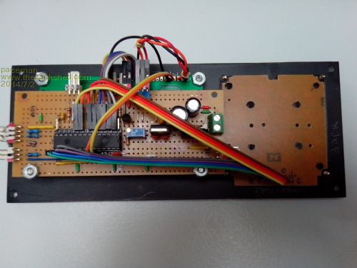
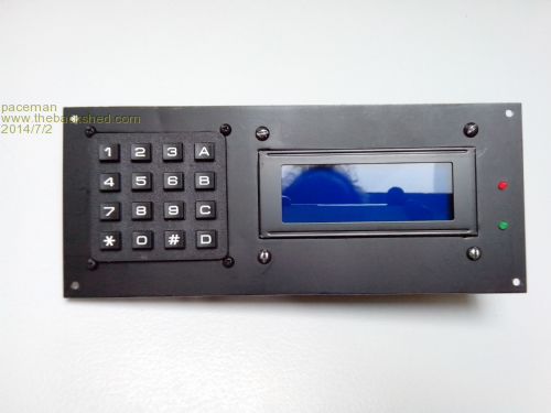
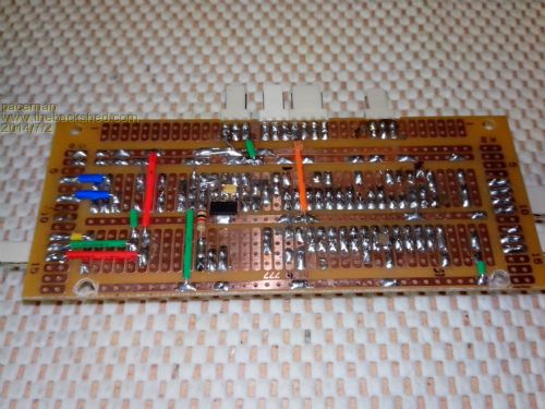
The keypad pin usage (seven lines or eight for a 4x4 pad) is worse than for the parallel display. That can be cut to one though if you use the single analogue input method for the keypad. There's a thread on the forum for that and it works well. It's an even bigger pain running the parallel keypad lines to the panel than it is for the display so using an I2C display and single line analogue keypad seems to me a very neat way of doing it and very economical on pin use. You can also use the 'spare' keys (* and #) for brightness control via PWM or with a 4x4 keypad control other functions. Even so, using a parallel 20x4 display and parallel 4x4 keypad I managed to also get the PWM display brightness control, lamp relay control (opto isolated), lamp 'ON' LED and a buzzer all controlled by the 24 pin chip and with two pins left over. Provision was also made on the board for the console Tx/Rx and ICSP connector (with some shared pins) but it all works. This is what the proto board looks like (actually it's half a proto board). I confess that I did use a couple of surface mounts bits to squeeze things in and the bottom as well as the top of the board was used, e.g. the 3.3v reg on the bottom. Greg 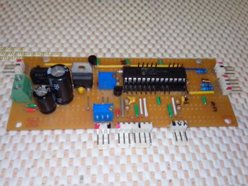
|
||||
| G8JCF Guru Joined: 15/05/2014 Location: United KingdomPosts: 676 |
That's impressive Greg, and SMD on stripboard ! Thanks for the tip about using an analogue input for the keypad, I'll search the Backshed and see if I can find that thread, much appreciated. Very many thanks Peter The only Konstant is Change |
||||
| Page 1 of 2 |
|||||
| The Back Shed's forum code is written, and hosted, in Australia. | © JAQ Software 2026 |
