
|
|
Forum Index : Microcontroller and PC projects : 4004 lcd display
| Author | Message | ||||
| viscomjim Guru Joined: 08/01/2014 Location: United StatesPosts: 925 |
Hi all, trying to implement a 4004 lcd display. Here is the link This display looks like it would work using uMite LCD feature, however the top 2 lines are controlled using E1, which is fine, however the bottom two lines use E2 for enable. Is there a way to implement this using maybe an extra output pin and after the first 80 characters are written, the E2 can be enabled and the balance can be written? Maybe an external logic gate or something? |
||||
CircuitGizmos Guru Joined: 08/09/2011 Location: United StatesPosts: 1427 |
Can't you just reissue the LCD INIT command for the next lines? Do this from within a function or two to encapsulate the complexity. Micromites and Maximites! - Beginning Maximite |
||||
Lou Senior Member Joined: 01/02/2014 Location: United StatesPosts: 229 |
Jim, I think Geoff would have to write code to support an LCD with another enable pin, E2. If you haven't already try hooking the E2 pin where E1 is now hooked, I think it will write to the bottom two lines. That would verify you need another control line (E2). I hooked up a 4x16 LCD I bought from Futurlec here , the BLUELCD16X4BL, to my 28 pin uMite LCD test jig and it works OK for the first two lines but when I write to lines 3 and 4 there is a four blank character offset to the text. Has anyone else tried to write to a 4x16 or any 4 line LCD ?? It could be a bug in the uMite code, I don't know. Lou Microcontrollers - the other white meat |
||||
| CircuitGizmos Guru Joined: 08/09/2011 Location: United StatesPosts: 1427 |
Or reinit the LCD setup for the next two lines. Use Pin X for the first enable (LCD INIT d4, d5, d6, d7, rs, PinX) the write to the top lines: LCD 1, pos, "Line 1" LCD 2, pos, "Line 2" Then reinit to use Pin Y for the second enable (LCD INIT d4, d5, d6, d7, rs, PinY) the write to the bottom lines: LCD 1, pos, "Line 3" LCD 2, pos, "Line 4" Encapsulate this in a function/sub. What happens if you increment position? For pos = 1 to 160 LCD 1, pos, "x" Next pos Do the x's wrap around to the other lines? Do you ever get an x in the right position? Do x's show up on line 3 or 4? Micromites and Maximites! - Beginning Maximite |
||||
| viscomjim Guru Joined: 08/01/2014 Location: United StatesPosts: 925 |
Hi CircuitGizmos, that is a brilliant idea. I will have to give that a whirl. No extra parts is great. Thanks for your brain power on that one!!! Lou, I have used several 2004 displays with WhiteWizzard 44 uMite board and have had no problems with the display. Haven't tried with 28 pin. |
||||
bigmik Guru Joined: 20/06/2011 Location: AustraliaPosts: 2981 |
Gday Jim, You could use a 74HC00 as shown and get what you want with one chip. and use one uMite pin (low for E1 and High for E2, just before you issue the LCD command) 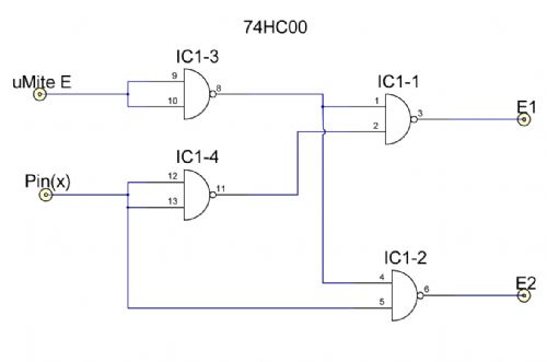
Truth Table 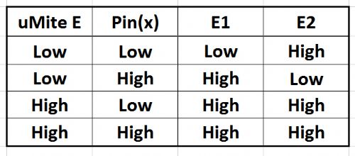
Of course pin14 of the 74HC00 goes to Vcc and 7 to GND Regards, Mick PS. Thanks for making me remember the `good old days' when I used to drink all Don's beer and breathe his cigarette smoke. Mick Mick's uMite Stuff can be found >>> HERE (Kindly hosted by Dontronics) <<< |
||||
donmck Guru Joined: 09/06/2011 Location: AustraliaPosts: 1314 |
Back in the days when doing a truth table for TTL logic, was almost an hourly event for us hey Mick? We didn't count sheep to go to sleep, we drew up a set of logic gates, and couldn't sleep until we had the answer. 
Just as well I gave up smoking 25+ years ago, otherwise we would both be deaded. Cheers Don... https://www.dontronics.com |
||||
| bigmik Guru Joined: 20/06/2011 Location: AustraliaPosts: 2981 |
Did I get it RIGHT though Donny? You used to slap me on the head like Benny Hill did to his Old Sidekick if I got it wrong. Of course a few beers was always a good encouragement those days. Mick Mick's uMite Stuff can be found >>> HERE (Kindly hosted by Dontronics) <<< |
||||
| donmck Guru Joined: 09/06/2011 Location: AustraliaPosts: 1314 |
Table looks good. That of course is why you went bald Mick. 
Cheers Don... https://www.dontronics.com |
||||
| paceman Guru Joined: 07/10/2011 Location: AustraliaPosts: 1329 |
I used a 4x20 in my UV timer Lou - works fine. The connections shown for your 40x4's have eight data pins - I guess they're OK to be setup as four though because that's how Geoff's commands assume. Greg |
||||
| Lou Senior Member Joined: 01/02/2014 Location: United StatesPosts: 229 |
CircuitGizmos, Yes, great idea init PinX, PinY. CG wrote: What happens if you increment position?
For pos = 1 to 160 LCD 1, pos, "x" Next pos Do the x's wrap around to the other lines? Do you ever get an x in the right position? Do x's show up on line 3 or 4? pos is a function and gave an error so I changed the name, put in a pause 100 before next to slow things down a bit, and tried the code. x's fill up line 1 then line 3, then about 1 second pause then line 2 prints an x in the first position, then about a 3 second pause and line 2 fills with x's then line 4 fills with x's, then a 3 second delay and some x's appear psuedo-randomly all over the screen and the program ends. If I change "1 to 160" to "1 to 96" I get the same sequence as above but the program ends as soon as the screen is filled. If I run "1 to 64" the program ends a couple seconds after filling lines 1 and 3 and the x in line 2 postion 1 and never writes the remainder of line 2 or line 4. That still doesn't help my mind with the 4 blank spaces in lines 3 and 4. Does it make any sense to you ?? Methinks some kind of LCD controller games going on inside this particular display, especially since a 4 line display works for paceman. I'm using 2x16 displays and they work fine so this doesn't hurt my project, it's just a point of curiosity. Thanks for the comments paceman and viscomjim, that helps. Lou Microcontrollers - the other white meat |
||||
| CircuitGizmos Guru Joined: 08/09/2011 Location: United StatesPosts: 1427 |
The 4004 LCD display is four lines of 40 characters. It uses two controller chips, though, so from a software perspective it appears to be two (stacked) 2 by 40 displays. 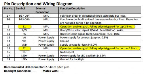
All of the lines are common, except for the two enable lines. If you use my trick I described above, then you can display text on all four lines. I would use a pull-up resistor of about 10k on the enable lines. When the micromite isn't driving the lines you don't want the enable line floating around. LCD communication is simple enough that you could use your own routines rather than the built-in LCD commands. Micromites and Maximites! - Beginning Maximite |
||||
| CircuitGizmos Guru Joined: 08/09/2011 Location: United StatesPosts: 1427 |
> pos is a function and gave an error so I changed the name, Oops. Oversight on my part. I was thinking LCD position. Forgot about POS. > x's fill up line 1 then line 3, then about 1 second pause then > line 2 prints an x in the first position, then about a 3 second > pause and line 2 fills with x's then line 4 fills with x's, then > a 3 second delay and some x's appear psuedo-randomly all over > the screen and the program ends. > If I change "1 to 160" to "1 to 96" I get the same sequence as > above but the program ends as soon as the screen is filled. > If I run "1 to 64" the program ends a couple seconds after > filling lines 1 and 3 and the x in line 2 postion 1 and never > writes the remainder of line 2 or line 4. Yup. This makes sense to me. The first character of line 1 is located in displayable memory (in the LCD) in location 0. The second character is located in memory location 1. The first character of line 3 is located in memory position 16. That is why the x jumps from the end of line 1 to the start of line 3. So as you fill character memory from 0 to 15 you fill line 1 position 1 to 16. Then when you write to character memory position 16 to 31 you fill line 3 1-16. Then as you write from memory 32 to 63 you write to nothing that can be displayed. That is why there is a pause. When you write to memory position 64, you write to line 2 position 1. writing to 64-79 fills line 2, writing to LCD memory locations 80-96 fills line 4. > That still doesn't help my mind with the 4 blank spaces in lines > 3 and 4. Does it make any sense to you ?? Yes/no/perhaps. :-) What I described above works for many LCD displays, but they are not all the same. Some of the starting positions for the lines are not exactly as I described. It depends on manufacturer. Could Geoff include LCD command variations for other LCD displays? He could, but blah! That would be a mess. If the LCD line number functionality doesn't work for your display, then manually adjust it yourself. Do this: LCD 1, 1, "Line 1" LCD 1, 1+L2OFFSET, "Line 2" LCD 1, 1+L3OFFSET, "Line 3" LCD 1, 1+L4OFFSET, "Line 4" Again this can be encapsulated in a function/sub. Micromites and Maximites! - Beginning Maximite |
||||
| CircuitGizmos Guru Joined: 08/09/2011 Location: United StatesPosts: 1427 |
Hmm. Have not tried this myself, so this theory could be ruined if there is any LCD erasing going on. Micromites and Maximites! - Beginning Maximite |
||||
| Lou Senior Member Joined: 01/02/2014 Location: United StatesPosts: 229 |
Thanks CG, Makes sense to me, line 1 address starts at Hex 80, line 2 starts at C0, line 3 starts at 94 and line 4 starts at D4. Just looked it up, I had read that before on the display data sheets but didn't take into account. If Geoff starts writing at 90 and D0 for lines 3 and 4 that explains the four character offsets I'm seeing on the display. No, wait - that would cut off the first four characters instead of offsetting them, wouldn't it ?? Oh well, I'm not using the 4 line display anyway. Lou Microcontrollers - the other white meat |
||||
| G8JCF Guru Joined: 15/05/2014 Location: United KingdomPosts: 676 |
Would this work ? '----------------------------------------------------------- ------- ' ' Print String to LCD ' ' SUB LCD_(LineNum,CharPos,Text$) LOCAL I IF LineNum=1 THEN I=(&H80 + CharPos-1) IF LineNum=2 THEN I=(&HC0 + CharPos-1) IF LineNum=3 THEN I=(&H94 + CharPos-1) IF LineNum=4 THEN I=(&HD4 + CharPos-1) LCD CMD(I) FOR I=1 TO LEN(Text$) LCD DATA(ASC(MID$(Text$,I,1))) NEXT I END SUB Probably NOT ! Please ignore this post 73 Peter The only Konstant is Change |
||||
| The Back Shed's forum code is written, and hosted, in Australia. | © JAQ Software 2026 |
