
|
|
Forum Index : Microcontroller and PC projects : DM enabling PWM
| Author | Message | ||||
Blackened Regular Member Joined: 11/08/2012 Location: AustraliaPosts: 66 |
Hello all, I'm struggling to find info regarding the hardware hack to allow the full PWM signal from the sound output. I've got a standard Duinomite, as well as a Mega. Ideally I'd like to switch the output level to suit sound OR PWM. Has anyone got a closeup shot of the board and could circle the offending components for me? I have tried in the past but couldn't be 100% certain, and now I actually have need of the PWM output. Thanks for any help. |
||||
| hitsware Guru Joined: 23/11/2012 Location: United StatesPosts: 535 |
I have Mega. 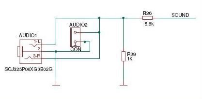
You can see R39 needs to be removed (trusting schematic and silkscreen) R39 and designator are easily seen on board just behind the audio out jacks. I have removed similar by breaking off with ice-pick ... |
||||
| hitsware Guru Joined: 23/11/2012 Location: United StatesPosts: 535 |
In order to make Color Maximite switchable (audio or pwm) 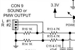
1) Remove R14 and R16 2) Connect 0.1uF capacitor from L #1 output to MMBasic pin 1 3) Connect 0.1uF capacitor from R #2 output to MMBasic pin 2 4) For audio (TONE or softened PWM): SETPIN 1, DOUT
SETPIN 2, DOUT
5) For PWM (fastest switching) SETPIN 1, OFF
SETPIN 2, OFF |
||||
| Blackened Regular Member Joined: 11/08/2012 Location: AustraliaPosts: 66 |
Excellent replies. Thanks Hitsware :) Now I just have to wait for my H-Bridge in the mail. |
||||
| hitsware Guru Joined: 23/11/2012 Location: United StatesPosts: 535 |
You're wellcome 
IMO the 1kOhm resistors shouldn't be there to start with. That way one could directly drive something like ... http://www.adafruit.com/products/355 |
||||
| Blackened Regular Member Joined: 11/08/2012 Location: AustraliaPosts: 66 |
I finally got around to removing the 1k pulldown resister from my DM. Although on my standard DM it's r42, not R39 as with the mega. Some testing resulted in the following: PWM output tested with multimeter and voltage 0 through 3.3V depending on duty. H-bridge wired as per diagram, and if I short it's PWM input pin to 5V the motor works However, the DM PWM output won't drive the motor? On the standard DM, the current limiting resister is R39 and 5.6K. Does this need to be bypassed? Or have it's value reduced? I guess I should just try it and see, but I was hoping someone might be able to confirm or deny before I go messing around lol Thanks everyone 
|
||||
| hitsware Guru Joined: 23/11/2012 Location: United StatesPosts: 535 |
> On the standard DM, the current limiting resister > is R39 and 5.6K. Does this need to be bypassed? > Or have it's value reduced? For a motor you need to try as much current as safe. I'd say 100 Ohm resistence PWM pin to motor . If no movement then you need active current boost . |
||||
| Blackened Regular Member Joined: 11/08/2012 Location: AustraliaPosts: 66 |
Thanks hitsware, This current project seems to have taken forever. DOA part from china, replacement components that didn't fix the original DOA problem. An error in the wiring diagram only found once second part arrived from china. Followed by Eureka! Google made it seem all so simple but it didn't turn out that way!! The first resistor I grabbed out of my junk box was 120 Ohm which worked a treat. In the end I decided not to bother making the output switchable. I think I'll just add a piezo for error beeps and remove the need for audio output. Just need to code up the full package now. Proportional fan control to maintain a set temperature in a heat exchanger. Thanks again for your invaluable help. I just wish I could contribute to this forum in a meaningful way, rather than just soaking up everyone else's expertise. In my defence, I do have some expertise, it just doesn't apply here (clearly!!) lol |
||||
Lou Senior Member Joined: 01/02/2014 Location: United StatesPosts: 229 |
Blackened, What H-Bridge are you using ?? I have just ordered some Microchip MCP14E8-E/P to try for low current inductor work. Thanks, Lou Microcontrollers - the other white meat |
||||
| Blackened Regular Member Joined: 11/08/2012 Location: AustraliaPosts: 66 |
Lou, One of these. Packaging was a bit dodgy, the first arrived DOA with the electrolytic partly crushed. Replacing didn't resurrect it I'm afraid and I had to wait a further 3 weeks :( |
||||
| hitsware Guru Joined: 23/11/2012 Location: United StatesPosts: 535 |
FWIW .... THESE are pretty nifty  |
||||
| The Back Shed's forum code is written, and hosted, in Australia. | © JAQ Software 2026 |
