
|
|
Forum Index : Microcontroller and PC projects : RS232 and PWM
| Author | Message | ||||
G.B.P. Newbie Joined: 13/08/2014 Location: AustraliaPosts: 16 |
Hi all, Just discovered the MicroMite and this forum. I am interested in programming the MicroMite to be able to drive 3 DC motors for a simulation program chair. I have written the program below which allows me to interact with the Simulation Engine with as many Axis as specified in the interface setting, in this case made up as follows: [A<Axis1><Axis2><Axis3>Z] The [A] marks the start and the [Z] the end of the transmission. PROGRAM: ............................. CPU 48 OPEN "COM1:115200: inv" AS #1 DIM dat AS STRING DO DO WHILE INPUT$(1,#1)<>"A" PRINT "Waiting" LOOP dat$ = "" DO x$= INPUT$(1,#1) IF x$ = "Z" THEN PRINT "Input: " + dat$ EXIT Do ELSE dat$ = dat$ + " " + x$ ENDIF LOOP dat$ = "" LOOP ............................... There are some delayed occurring between the transmission but these are not so relevant during the simulation. 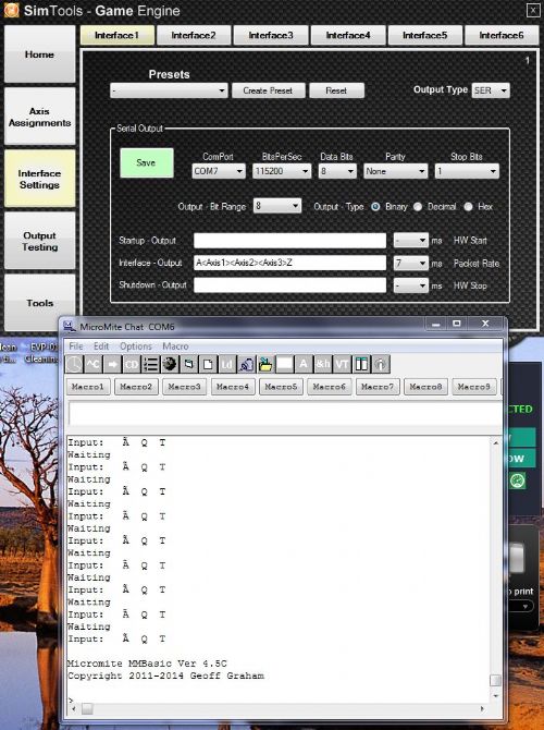
Biggest problem is that I cannot relate the input values to any specific coding.. 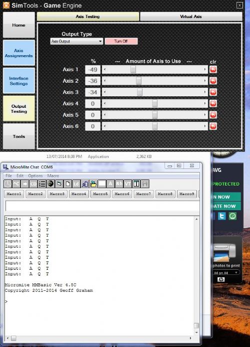
These values change when the Axis Testing Sliders are used. Can anyone suggest where or what I do incorrect so that possible to receive a whole number instead of these different ASCII codes and extensions.. Thanks |
||||
halldave Senior Member Joined: 04/05/2014 Location: AustraliaPosts: 121 |
Maybe the 3 values are delimited by a space x <space> y <space> z these may also be ascii equivalents to convert would be x=asc(left$(datout$,1)) y=asc(mid$(datout$,3,1) z=asc(right$(datout$,1) OPEN "COM1:115200: inv" AS #1 DO ' read 1 character dat$=INPUT$(1,#1) if dat$ = "A" then ' Start of Record datout$="" endif if dat$="Z" then ' End of Record print datout$ x=asc(left$(datout$,1)) y=asc(mid$(datout$,3,1) z=asc(right$(datout$,1) print x, y, z endif if dat$<>"A" and dat$<>"Z" then datout$=datout$+dat$ endif LOOP |
||||
TassyJim Guru Joined: 07/08/2011 Location: AustraliaPosts: 5905 |
It is difficult if we don't know what format the data is being sent as. Is it ASCII or HEX bytes? Try changing dat$ = dat$ + " " + x$ to dat$ = dat$ + " " + str$(asc(x$)) and see if that makes more sense. Jim VK7JH MMedit MMBasic Help |
||||
| halldave Senior Member Joined: 04/05/2014 Location: AustraliaPosts: 121 |
See where is says output type have you played around with different values, binary, decimal, hex?? |
||||
| G.B.P. Newbie Joined: 13/08/2014 Location: AustraliaPosts: 16 |
Hi Halldave, The output is binary and your sample program works perfectly, needed minor adjustments on the X,Y,Z format.. Input ranges from 0 to 255.. These are the values required for setting the motors directions further on in the program.. DO ' read 1 character dat$=INPUT$(1,#1) if dat$ = "A" then ' Start of Record datout$="" endif if dat$="Z" then ' End of Record x=asc(left$(datout$,1)) y=asc(mid$(datout$,2,1)) z=asc(right$(datout$,1)) print x, y, z endif if dat$<>"A" and dat$<>"Z" then datout$=datout$+dat$ endif LOOP 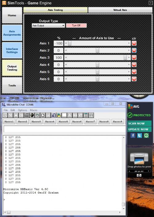
Thank you all for such fast response, I can now continue with the rest  |
||||
| halldave Senior Member Joined: 04/05/2014 Location: AustraliaPosts: 121 |
your welcome |
||||
| G.B.P. Newbie Joined: 13/08/2014 Location: AustraliaPosts: 16 |
Hi everyone, I am getting closer to the final working prototype of my 3DOF Micromite controller. I have one more question to ask regarding the different possible inputs to the Micromite unit. Currently, the program is designed to receive the simulation game data trough pin 22/21 (Com1 @ 115,200 Baud)via the cheap diode/resistor connections, while the programming is done through pin 12/13 via a USB-Serial adaptor. (Freetronic 16u2 USB@ 38,400 Baud) I am designing the electronic schematic and PCB (attached) to allow the use of only one USB-Serial adaptor for both cases so that beside avoiding a separate 5V supply, the changes between programming and working is very simple. This requiring only to swop J2a with J2b and adjust baud rate. 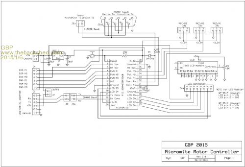
The issue is that if I connect the USB-Serial TX and Rx to pin 12/13 and change baud rate there is still no communication and the MM stands. With the Freetronic unit Rx light on full time. Is there a specific method or command required to activate this communication? Thanks 2015-01-06_071631_3DOF_with_Micromite.zip |
||||
