
|
|
Forum Index : Microcontroller and PC projects : [MMBasic]G8JCF Libraries
| Page 1 of 2 |
|||||
| Author | Message | ||||
| G8JCF Guru Joined: 15/05/2014 Location: United KingdomPosts: 676 |
Hi I have created a website http://www.g8jcf.dyndns.org/mmbasic/ from which one can download various MMBasic related bits 'n pieces. 73 Peter The only Konstant is Change |
||||
bigmik Guru Joined: 20/06/2011 Location: AustraliaPosts: 2981 |
Gday Peter, Looks very interesting, Now all who frequent this board know that as a programmer ... I suck!! .. 
Is the LCDI2CLib V3 supposed to run AS-IS? I thought I would modify its settings to suit my IO Panel and it bombs out on line 319 with UNKNOWN COMMAND, so I loaded your untouched code and it did the same.. straight after you press a key when prompted. Also is the R/W bit not able to be changed? You mention it is connected to p1 but obviously if you have the data bits on that nybble you cant have rw there. Confused.. Mick Mick's uMite Stuff can be found >>> HERE (Kindly hosted by Dontronics) <<< |
||||
| G8JCF Guru Joined: 15/05/2014 Location: United KingdomPosts: 676 |
Sorry Mick Mea Culpa, I mixed up the test suite from V2 with the code in V3, so I've corrected the code in the test suite, and it should all run now Please goto http://www.g8jcf.dyndns.org/mmbasic/ and download the updated library (V4). The Library includes a test suite so it should just run. For your board, you will need to change 'Initialise the I2C LCD device 'LCDI2C_Init I2CAddr,NibPos,RSBitNo,ENBitNo,BLBitNo LCDI2C_Init &H27,1,0,2,3 to (I think) 'LCDI2C_Init I2CAddr,NibPos,RSBitNo,ENBitNo,BLBitNo LCDI2C_Init &H27,0,4,7,6 ie use P0~P3 as data nibble P4 is RS P7 is EN P6 is Backlight Control The library doesn't use R/W at all. Once again, apologies. Hope V4 works for you. Peter The only Konstant is Change |
||||
| bigmik Guru Joined: 20/06/2011 Location: AustraliaPosts: 2981 |
Hi Peter, I tried it (using LCDI2C_Init &H20,0,4,7,5 ) as I have it set for 20H and BLight is on P5.. but it shows the following: press 1 Full 4 lines of solid blank press 2 backlight off press 3 backlight on still blank press 4 backlight on still blank press 5 backlight on still blank press 6 flashing block cursor on line 2 pos 2 press 7 rapid blinking all over the screen (nothing intelligible) Here is the schematic for the LCD module 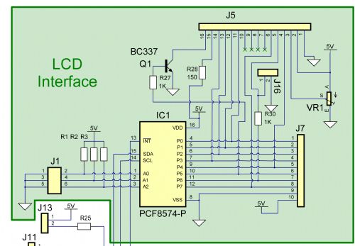
Regards, Mick EDIT **** J5 is the LCD Module. Mik Mick's uMite Stuff can be found >>> HERE (Kindly hosted by Dontronics) <<< |
||||
| G8JCF Guru Joined: 15/05/2014 Location: United KingdomPosts: 676 |
Hi Mick I'll take a look tomorrow (UK) morning. Can U confirm please D0-D3 is on P0-P3 RS is on P4 Backlight is on P6 EN is on P7 73 Peter The only Konstant is Change |
||||
| bigmik Guru Joined: 20/06/2011 Location: AustraliaPosts: 2981 |
Gday Peter, When you say D0-D3 I assume you mean LCD D4 to D7 (as 4 bit mode use the high order bits.. The only correction to the above is Backlight is on P5 not P6. A full list is as follows: P0 = DB4 P1 = DB5 P2 = DB6 P3 = DB7 P4 = RS P5 = BackLight P6 = RW (NO RW control so RW linked to GND) P7 = EN A modified circuit of the LCD interface is here: 2014-08-20_021053_LCD_Circuit.zip Regards, Mick PS. I do have working code for the display if you need it (I doubt you do) Could it need a longer delay on my displays than yours? Mick Mick's uMite Stuff can be found >>> HERE (Kindly hosted by Dontronics) <<< |
||||
| G8JCF Guru Joined: 15/05/2014 Location: United KingdomPosts: 676 |
Hi Mick LCDI2C_Init I2CAddr,NibPos,RSBitNo,ENBitNo,BLBitNo LCDI2C_Init &H20,0,4,7,5 looks correct to me P0~P3 -> DB4~DB7 -> 11~14 P4 -> RS -> 4 P7 -> EN -> 6 P5 -> BL -> 15 via Q1 0V -> RW -> 5 I'm really puzzled, I've tested the library on 3 different LCD displays (5V) including a 4 x 20 line display and they all worked without any code changes. The library runs the I2C at 400KHz - I use 4K7 pullups to 5V. I think the best way to debug what is wrong may be if you can send me your working code and I will do a comparison/run it up. Sorry it's not just working :( OK ? Peter The only Konstant is Change |
||||
| bigmik Guru Joined: 20/06/2011 Location: AustraliaPosts: 2981 |
Gday Peter, Aha, I think thats it.. The PCF8574 data sheet specifies the MAX clock speed is 100kHz... I will try it when I can later tonight.. Mick Ps. I love the way you wrote the lib.. It was easy enough for me to follow. Mick Mick's uMite Stuff can be found >>> HERE (Kindly hosted by Dontronics) <<< |
||||
| bigmik Guru Joined: 20/06/2011 Location: AustraliaPosts: 2981 |
Peter, Sorry to say I couldnt get that to work (changing to 100kHz) I also tried 3 other displays to no effect.. I have just had another thought, I will try my Prototype board which has chips bought from RS components... these ones were bought from CHina (still works with the following example files) 2014-08-20_110619_I2C_LCD_works_4x20.zip Regards, Mick EDIT **** Nope! No difference with theProto/RS Components chips. It has got me. Mik Mick's uMite Stuff can be found >>> HERE (Kindly hosted by Dontronics) <<< |
||||
halldave Senior Member Joined: 04/05/2014 Location: AustraliaPosts: 121 |
try Peter's code on the cheap chinese i2c lcd boards you have and see if it works i also tried against the PCF8574 in the io board and get the same results as you mick i sent Peter and i2c io board today in the mail,,,, we may have an answer in a week once he has a chance to build it yet i can drive the display based on your code.... let me do a compare at work tmoz between the two regards David |
||||
| G8JCF Guru Joined: 15/05/2014 Location: United KingdomPosts: 676 |
I'm sorry to hear of these probs. Are you running the PCF8574 at 5V ? I've just finished the I2C Keypad library (sent to David for testing) and it works at 400KHz using the really cheap PCF8574 chips from China. I run the PCF8574 at 5V, but the INT pullup goes to 3V3 so that it can feed one of the uMite INT input pins (which are not 5V tolerant). Anyway, as soon as the I/O Panel arrives from David, I'll get it wired up and tested. I do have a spare 16x2 LCD, and some PCF8574 chips, so I could breadboard that setup and do some testing if speed is of the essence. :( :( Peter The only Konstant is Change |
||||
| halldave Senior Member Joined: 04/05/2014 Location: AustraliaPosts: 121 |
Peter, this is what prototyping is all about.... others down the track will benefit.. you have good solid code... it may need to cater for a few extra variables remember you only get thick skin through scarring 
regards David |
||||
Lou Senior Member Joined: 01/02/2014 Location: United StatesPosts: 229 |
Mick, I don't know if it matters but I have LCD pins 7,8,9 and 10 (D0-D3) on my displays grounded, looks like yours are open on the schematic. Good luck, Lou Microcontrollers - the other white meat |
||||
| G8JCF Guru Joined: 15/05/2014 Location: United KingdomPosts: 676 |
Hi David Yup prototyping is what has to be done, but I'm still puzzling why the code is failing.   The only Konstant is Change |
||||
| bigmik Guru Joined: 20/06/2011 Location: AustraliaPosts: 2981 |
Gday Peter, The keypad routine work beautifully .. Yes I am running them at 5V as the LCD wont run at 3v3.. basically the board runs with what ever voltage you plug into Vcc, so yes my pullups would be at 5v but with 10k pullups.. I think it would be safe... I will investigate that.. It certainly works though.. They keypad routine is great.. Did you intend A,B,C&D to returne 21-22-23-24? Mick I can knock up your circuit but prob not till the weekend my day is full tomorrow. I am sure your LCD circuit will work with your code and that it is a funny in the logic. I did notice that you had a \16 instead of a /16 for the divide but both seemed to be acceptable. Mick Mick's uMite Stuff can be found >>> HERE (Kindly hosted by Dontronics) <<< |
||||
| bigmik Guru Joined: 20/06/2011 Location: AustraliaPosts: 2981 |
Yes Lou, Mine are floating but I have always used them this way.. And as they work with my hack of John Gerrards code I dont think that that is the answer.. Just from observations it looks to me that the problem is when you write text as the initialisation seems to work and backlight control is fine and cursor movements are fine (as far as I can determine.) Regards, Mick Mick's uMite Stuff can be found >>> HERE (Kindly hosted by Dontronics) <<< |
||||
| G8JCF Guru Joined: 15/05/2014 Location: United KingdomPosts: 676 |
Hi Mick Phew, so the I2CKeyPad code works, that's great news, thanks for the update. The returned keycodes are as per the 4.5 Micromite Manual, page 20, so as to make conversion to I2C keypads as painless as possible. While the I2CLCD is running, hit ctrl+C and then from the command line do lcdi2c_backlight 1<enter> which should turn ON the backlight and then lcdi2c_backlight 0<enter> which should turn OFF the backlight. If these work, then the I2C parts of my library at least must be working. From your observations above, I'll take a really close look at the text writing code now. 73 Peter The only Konstant is Change |
||||
| G8JCF Guru Joined: 15/05/2014 Location: United KingdomPosts: 676 |
Hi Mick I've been studying both my code and Garrad's, and there seems to be a significant difference between the two when it comes to addressing Line 1 of the LCD. in my code, at line 102, I send &H80 to position the cursor whereas in I2C4lineclock.bas at line 102, or ICDLCDWorks2x16.bas at line 137 it sends &H02 to position the cursor. You could try changing line 102 in my library to &H02 from &H80 and see if that makes any difference. Peter The only Konstant is Change |
||||
| G8JCF Guru Joined: 15/05/2014 Location: United KingdomPosts: 676 |
\ is the nearest thing to Shift Right ! PS, I just changed my line 102 to use &H02 instead of &H80, and what a strange display I get, various weird characters ! Peter The only Konstant is Change |
||||
| G8JCF Guru Joined: 15/05/2014 Location: United KingdomPosts: 676 |
Mick, David Found the bug ! It's in SUB LCDI2C_DATA(Byte) 'Send Hi Nibble LCDI2C_DirectSend((Byte AND &HF0) OR LCDI2C_RSDataMask) 'Send Lo Nibble LCDI2C_DirectSend(((Byte AND &H0F) * 16) OR LCDI2C_RSDataMask) END SUB The problem is with the "OR LCDI2C_RSDataMask", this sub assumes that the RSDataMask is in the lower 4 bits which of course it's not on your board Mick. I'll have to do some thinking about how to fix this. This would explain why Mick thought it had initialised OK, but went wrong when writing text, text needs RS set high, whereas sending commands needs RS set Low. Well at least I know what's wrong, now to fix it ! Take care Peter The only Konstant is Change |
||||
| Page 1 of 2 |
|||||
| The Back Shed's forum code is written, and hosted, in Australia. | © JAQ Software 2026 |
