
|
|
Forum Index : Microcontroller and PC projects : Switching 3v3....
| Author | Message | ||||
Grogster Admin Group Joined: 31/12/2012 Location: New ZealandPosts: 9066 |
Hi folks. 
I have a network module in my latest concept - a WizNet 107, which needs 3v3 @ 200-250mA. That is no problem, as I supply it via a 3940 regulator. The issue I have is switching the juice to it. With only 3v3 to play with, and a relatively high current consumption, it is really quite important that there is no voltage drop across transistor type enable circuits. My first idea was this: 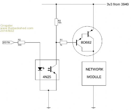
This WOULD work, but my concern is voltage-drop as mentioned above. Not really much of a problem if the network module had a greater voltage tolerance, but it does not, from what I can see in the datasheet - it is 3v3 - that's it. So, using the above diagram, I'd expect a 0.6v voltage-drop across the BD682, leaving 2.7v on the module, and that would be below the specified 3v3. How about using a MOSFET instead of a 682? At the moment, I have it working via a relay, and that is working fine, but relays are expensive compared to transistors for basic power switching. Smoke makes things work. When the smoke gets out, it stops! |
||||
| WhiteWizzard Guru Joined: 05/04/2013 Location: United KingdomPosts: 2794 |
Hi Grogs, How about simply switching the Gnd line with a MOSFET driven by the I/O pin. That will work ok. Use something like an NTR4170N MOSFET (SMD) - then no more components apart from the MOSFET. If you have June edition of Silicon Chip (the one with Part 2 of Geoff's series) then take a look at the circuit diagram for the Touch-Screen Digital Audio Recorder on Page 43. There you will see three of these MOSFETS in use doing exactly what you desire. WW edit: Switching the Gnd also means you can use whatever +v supply you like/need  For everything Micromite visit micromite.org Direct Email: whitewizzard@micromite.o |
||||
| Grogster Admin Group Joined: 31/12/2012 Location: New ZealandPosts: 9066 |
Cool, thanks - I will check out that article - I have that issue. Smoke makes things work. When the smoke gets out, it stops! |
||||
bigmik Guru Joined: 20/06/2011 Location: AustraliaPosts: 2870 |
Hi Grogster, Is the 3v3 only used for the module ? Also what s your supply voltage to your reg.. Using the transistor to switch the gnd line instead of the power wont make any difference to swtching the 3v3 as the voltage drop across the transistor will still be the same and reduce the voltage across the power and gnd of your module. I dont have any experience with mosfets so i cant comment on voltage drop across them.. I would look at using a LDO vreg such as lm1117 and. Using the transistor to switch the 5v or whatever you supply it with. Mick Mick's uMite Stuff can be found >>> HERE (Kindly hosted by Dontronics) <<< |
||||
| WhiteWizzard Guru Joined: 05/04/2013 Location: United KingdomPosts: 2794 |
Hi Mick, Switching the Gnd line will mean there is no current drain when the device is 'off'. If you switch the =ve supply then there will still potentially be leakage currents (through data/control lines) which can be significant. This probably won't be an issue for Grogs; however it is good practice when designing battery operated devices to gather every last bit of current saving to maximise battery life. Also as previously mentioned, it also allows you to have whatever +v supply to the device; independent of the controlling host. To reduce electrical noise on the Network Module, I would have a dedicated LDO/Vreg to supply the module and then switch the GND with a MOSFET. That way, minimal current when off, and minimal components (just one mosfet). There are many ways to achieve what Grogs is after - this is just the way I would approach it . . . . WW For everything Micromite visit micromite.org Direct Email: whitewizzard@micromite.o |
||||
| Grogster Admin Group Joined: 31/12/2012 Location: New ZealandPosts: 9066 |
I'm feeding the 3940 from a 7805. This is the suggested arrangement in the 3940 datasheet. Not 7805 specifically, but that the input voltage to the 3940 should be from a 5v regulated source, so I am feeding it from a 7805. I have done this for other things in the past, and have had no issues there. My test rig for the 107 network module even used the exact same setup. The 3940 feeds other things on the board that need 3v3, such as the SD card, and all the 10k/1k pull-ups on any I/O pin to the PIC32 module.(I/O pins are pulled to deck to trip them kind of arrangement) I did look at using some LDO regs I have here in stock(MCP1703-33's), but they have a maximum load current of 200mA, and I figured I would be pushing things by using one of those, so decided to hop on to the 3940's output which is capable of 1A easy. EDIT: @ WW - Yes, I think you are onto something with the MOSFET idea. I have looked at the schematic on page 48 of June SC, and can see how they are doing it, so think this is probably the best idea. From what I can remember, once the gate voltage on the FET is present, the Source-to-Drain resistance is very nearly zero ohms, so there should not be a 0.6v drop when using a FET over a BJT - correct? Smoke makes things work. When the smoke gets out, it stops! |
||||
| WhiteWizzard Guru Joined: 05/04/2013 Location: United KingdomPosts: 2794 |
Correct - 'On' resistance will be in region of 50mOhm (milli - not Mega!), so applying Ohm's law implies near zero voltage drop. WW For everything Micromite visit micromite.org Direct Email: whitewizzard@micromite.o |
||||
jman Guru Joined: 12/06/2011 Location: New ZealandPosts: 711 |
Hi I use this method . This a logic FET a big large for your application but you get the idea 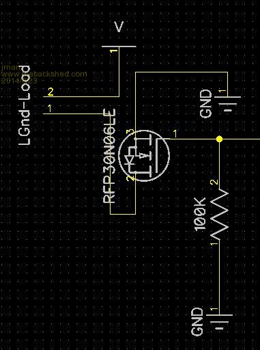
Jman |
||||
OA47 Guru Joined: 11/04/2012 Location: AustraliaPosts: 911 |
Graeme, I have successfully used an opto and mosfet to regulate solar charging in one of my projects: 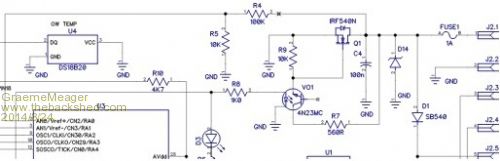
2014-08-24_030111_solarshutdown.zip The mosfet has a switch resistance of less than 0.4 ohm so I can short circuit the solar panel without having any heat issues. Maybe you could do something similar. The solar voltage is measured with the 10K/100K resistors (R4,R5) but I activate the shutdown by monitoring the SLA battery volts on the other side of D1 in a similar fashion. The mosfet (wrongly represented with an inbuilt diode) is held off with R9 until the opto is activated. D12 is a safety measure just in case the software stalls. GM |
||||
| Grogster Admin Group Joined: 31/12/2012 Location: New ZealandPosts: 9066 |
Thanks Graeme, jman and WW for your replies - I think this is definetly the way to do it. Appreciated. I will use a FET as suggested and shown instead of my original idea.Smoke makes things work. When the smoke gets out, it stops! |
||||
| bigmik Guru Joined: 20/06/2011 Location: AustraliaPosts: 2870 |
Lads, I admit to not being 100% up to FETs and their ilk but from what I have read they still appear to have about a 1V drop across them, That doesnt help if you still need 3v3 exactly.. What am I missing? Is the 1V only at high currents? Mick Mick's uMite Stuff can be found >>> HERE (Kindly hosted by Dontronics) <<< |
||||
| Grogster Admin Group Joined: 31/12/2012 Location: New ZealandPosts: 9066 |
I did not think they had essentially any voltage-drop, due to the very low source-Drain resistance once a Gate voltage is applied? I will wait and see what others here come up with before making any firm decision. Unfortunately, I have no FET's at all in stock - I can easily get some though. I'm probably like you, Mick - a student of bi-polar transistors!  Smoke makes things work. When the smoke gets out, it stops! |
||||
| bigmik Guru Joined: 20/06/2011 Location: AustraliaPosts: 2870 |
Lads, I would be inclined to add another 3v3 regulator and switch the 5V (or GND) line to it. Although there may be difficulties there as well with 1.1V lost in the LDO VReg that only leaves .6v up your sleeve for your`switch' If you can feed from a 6-8V source it would work very well. Regards, Mick Mick's uMite Stuff can be found >>> HERE (Kindly hosted by Dontronics) <<< |
||||
| Grogster Admin Group Joined: 31/12/2012 Location: New ZealandPosts: 9066 |
Perhaps I should just go back to the relay I was using - zero voltage-drop.
This IS working, but I figured that a more solid-state arrangement would be a better idea. Still interested in any comments/suggestions/pills/booze.... Smoke makes things work. When the smoke gets out, it stops! |
||||
